
Mixed structure method of layout of different size elements to optimize the area usage on a wafer

a technology of mixing structure and layout, applied in the field of semiconductor devices, to achieve the effect of increasing the functionality of a given area, and reducing the cost per unit area

Inactive Publication Date: 2018-06-07
AVERY DENNISON CORP
View PDF13 Cites 0 Cited by
  • Summary
  • Abstract
  • Description
  • Claims
  • Application Information

AI Technical Summary

Benefits of technology

The patent describes a semiconductor wafer device that includes components of different sizes. The device also contains a 3-D stack of components, which means the components are placed on top of each other. This allows for increased functionality in a specific area. One example is a small digital processor placed on top of a larger sensor or display. The 3-D stack creates a more efficient use of space, making it easier to create complex devices on a small wafer.

Problems solved by technology

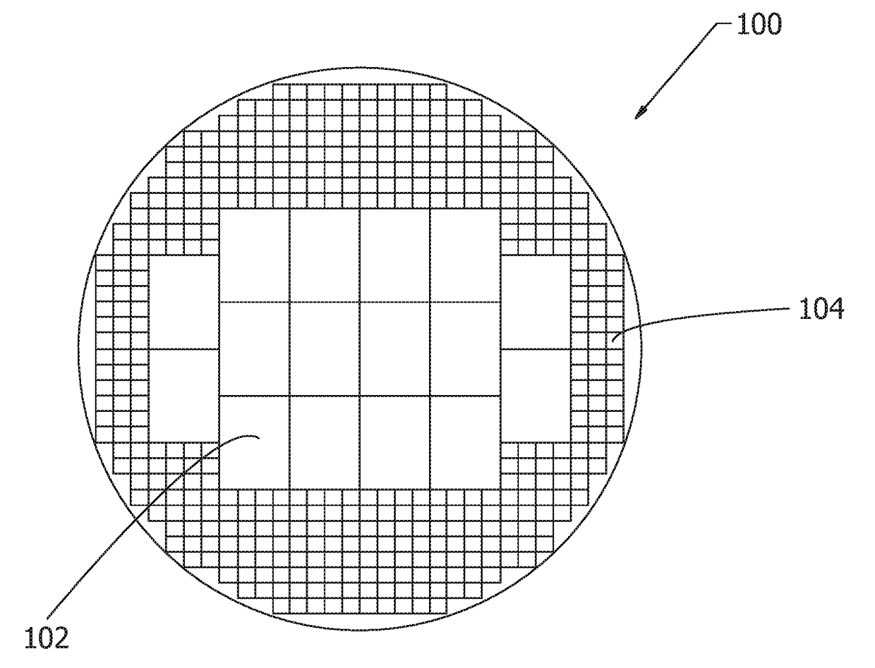
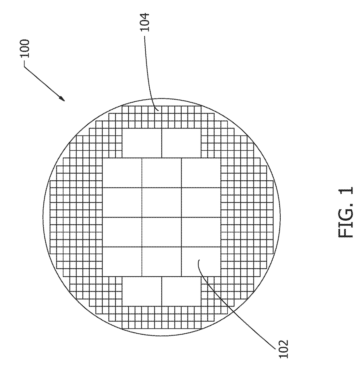
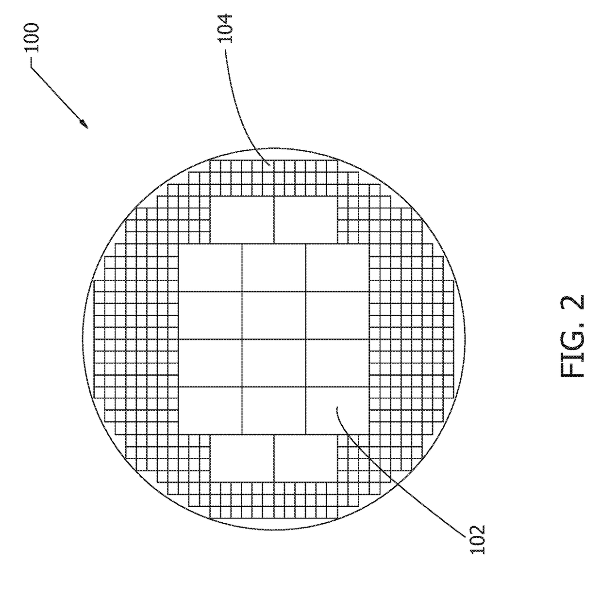
The small devices act as fill in elements for the wafer, as the plurality of large devices do not efficiently fill in the wafer.

Method used


Image

  • Mixed structure method of layout of different size elements to optimize the area usage on a wafer
  • Mixed structure method of layout of different size elements to optimize the area usage on a wafer
  • Mixed structure method of layout of different size elements to optimize the area usage on a wafer

Examples


Embodiment Construction

[0014]The innovation is now described with reference to the drawings, wherein like reference numerals are used to refer to like elements throughout. In the following description, for purposes of explanation, numerous specific details are set forth in order to provide a thorough understanding thereof. It may be evident, however, that the innovation can be practiced without these specific details. In other instances, well-known structures and devices are shown in block diagram form in order to facilitate a description thereof.

[0015]New processes for creating chips can make relatively large flexible parts that can be used as straps which can be used on antennas but also as bridges for high frequency antennas. These larger devices do not efficiently fill the wafer area, so in this invention a smaller part is also created on the wafer. Thus, the present invention discloses a semiconductor wafer device that comprises a round wafer with a large surface area and a low cost per unit area. Th...


PUM


Abstract

A semiconductor wafer device that comprises a round wafer with a large surface area and a low cost per unit area is disclosed. The semiconductor wafer device comprises mixed size elements, such that a plurality of large devices are manufactured on the wafer, as well as a plurality of small devices are manufactured on the wafer. The small devices act as fill in elements for the wafer, as the plurality of large devices do not efficiently fill in the wafer. Typically, the large devices comprise strap or interposer devices and the small devices comprise chip devices. The chip devices attach to small RFID antennas and the interposer devices attach to larger structures, such as high frequency tags where the strap / interposer can act as a bridge from the center of an antenna coil to the outside.

Description

CROSS REFERENCE TO RELATED APPLICATION(S)[0001]The present application claims priority to and the benefit of U.S. Provisional Utility Patent Application No. 62 / 428,873 filed Dec. 1, 2016, which is incorporated herein by reference in its entirety.BACKGROUND[0002]The present invention relates generally to a semiconductor wafer device. Specifically, the semiconductor wafer device comprises a round wafer with a large surface area and a low cost per unit area. The semiconductor wafer device comprises mixed size elements, such that a plurality of large devices are manufactured on the wafer, as well as a plurality of small devices are manufactured on the wafer.[0003]In the manufacture of semiconductor devices, a plurality of integrated circuits are simultaneously prepared in a semiconductor wafer through the use of conventional photolithographic techniques. It is also convenient to provide a plurality of secondary devices such as contact pads, test monitor devices, devices for measurement ...

Claims


Application Information

Patent Timeline
Patent Type & Authority Applications(United States)
IPC IPC(8): H01L23/66H04B1/40
CPCH01L23/66H04B1/40H01L2223/6677H01L2924/1434H01L2924/1421G08B13/2417G08B13/2431
Inventor FORSTER, IAN J.
Owner AVERY DENNISON CORP
Learn More