Rotary printing machine

a rotary printing machine and printing technology, applied in the field of printing machines, can solve the problems of increased printing time, low printing efficiency, unfavorable manual printing registration control, etc., and achieve the effect of reducing labor and time costs and upgrading printing efficiency

Active Publication Date: 2018-06-14
ATMA CHAMP ENTERPRISE
View PDF7 Cites 0 Cited by
  • Summary
  • Abstract
  • Description
  • Claims
  • Application Information

AI Technical Summary

Benefits of technology

[0025]The rotary printing machine of the present invention is characterized in that the clamping units provided on the printing cylinder work in cooperation with the mechanically operated feeding control mechanism and unloading control mechanism, it is therefore possible to determine the operating states of the clamping units at the feeding position and the unloading position. With these arrangements, the workpiece on the rotary printing machine can be printed only once without the need of adjusting the rotary printing machine. On the other hand, when the workpiece on the rotary printing machine is to be repeatedly printed multiple times, simply adjust the feeding control mechanism and the unloading control mechanism for the clamping units to maintain the clamped state, and a three-dimensional printed pattern with multiple layers of ink can be formed on the workpiece.
[0026]Moreover, in the rotary printing machine of the present invention, the use of dual clamping units along with the inkjet member or a screen carrier enables a fully automatic three-dimensional electronic printing operation, which can effectively reduce the labor and time costs to upgrade the printing efficiency.

Problems solved by technology

Since the screen printing machine with one single clamping unit can complete only one printing operation when the printing cylinder rotates a full circle of 360 degrees, the printing efficiency thereof is very low.
However, most screen printing machines available in the market are designed for the workpiece to be printed only once.
By doing this, the time for printing is increased and it is uneasy to control the accuracy of manual printing registration.
Accordingly, the printing quality and productivity are relatively low, and the complicated procedures for the three-dimensional printing also largely increase the cost of the screen printed pattern.

Method used


Image

  • Rotary printing machine
  • Rotary printing machine
  • Rotary printing machine

Examples


Embodiment Construction

[0043]The present invention will now be described with a preferred embodiment thereof and by referring to the accompanying drawings.

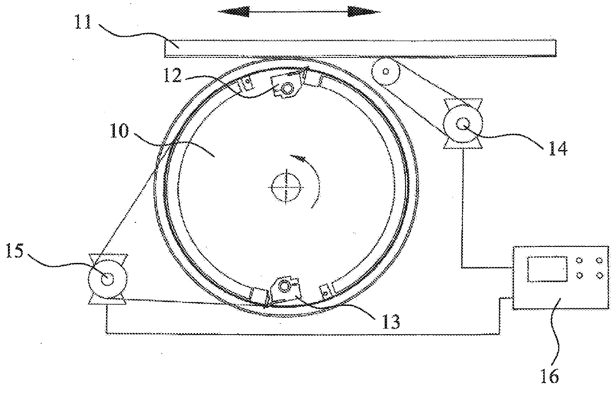
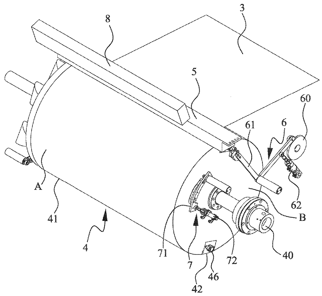
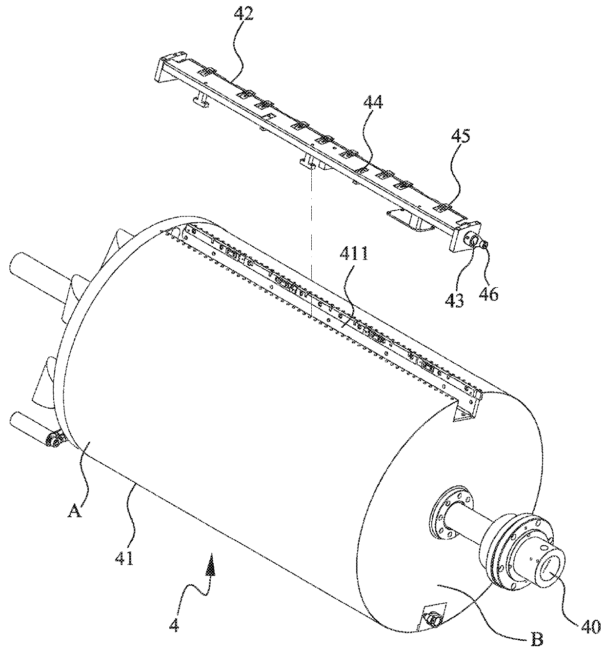
[0044]Please refer to FIG. 2. A rotary printing machine 2 according to a preferred embodiment of the present invention is mainly characterized by improving a printing mechanism located between a feeding mechanism and an unloading mechanism, so that the rotary printing machine 2 can be selectively operated for a workpiece 3 to be printed only once or be repeatedly printed multiple times in a continuous manner. The rotary printing machine 2 of the present invention includes a printing cylinder 4, a printing unit 5, a feeding control mechanism 6, an unloading control mechanism 7, and a drying unit 8.

[0045]The printing cylinder 4 is driven to rotate by a servomotor (not shown), which enables precisely controlled rotational speed and accuracy of the printing cylinder 4. The printing unit 5 is installed over the printing cylinder 4 and located adjacent to a p...


PUM


Abstract

A rotary printing machine includes a printing cylinder, at least one clamping unit mounted on a printing surface of the printing cylinder, and a feeding control mechanism and an unloading control mechanism mounted to a lateral side of the printing cylinder for changing the clamping state of the clamping unit. When the clamping unit is moved to an unloading position, the unloading control mechanism can be operated to control the clamping unit to maintain a closed state, so that a workpiece can be brought by the printing cylinder to a feeding position again. Then, the feeding control mechanism can be operated to control the clamping unit at the feeding position to maintain a clamped state, so that printing can be repeated on the workpiece to form multiple layers of ink and create three-dimensional printed layers showing a specific visual effect.

Description

FIELD OF THE INVENTION[0001]The present invention relates to a printing machine, and more particularly to a rotary printing machine, with which a workpiece can be printed only once or be repeated printed multiple times in a continuous manner.BACKGROUND OF THE INVENTION[0002]Generally, a screen printing machine includes only one clamping unit on a printing cylinder thereof. When the clamping unit is located at a feeding position, it clamps a workpiece in place on the printing cylinder. Then, the printing cylinder continuously rotates and brings the workpiece to a position corresponding to a screen carrier, and the screen carrier is caused to move horizontally while the printing cylinder rotates, so that a printed pattern is formed on the workpiece that is located between the printing cylinder and the screen carrier. Thereafter, when the workpiece is moved to an unloading position, the clamping unit releases the workpiece, so that the workpiece leaves from the printing cylinder and th...

Claims


Application Information

Patent Timeline
Patent Type & Authority Applications(United States)
IPC IPC(8): B41F3/54
CPCB41F3/54B41F15/0804B41F15/22B41F21/10B41J13/223B41J11/00214B41F21/00B41F21/104
Inventor CHEN, TUNG CHIN
Owner ATMA CHAMP ENTERPRISE
Why Eureka
Try Eureka