Front End Motor-Generator System and Hybrid Electric Vehicle Operating Method

Active Publication Date: 2018-06-14
BENDIX COMML VEHICLE SYST LLC
View PDF5 Cites 19 Cited by
  • Summary
  • Abstract
  • Description
  • Claims
  • Application Information

AI Technical Summary

Benefits of technology

[0043]In addition to the already mentioned features, capabilities and advantages, the present invention's front end motor-generator approach has the important advantage of not requiring substantial modifications to the front of a vehicle, such as lengthening of the nose of a commercial vehicle tractor or increasing the size of an engine compartment of a diesel-powered municipal bus. This is directly the result of the FEMG system being readily accommodated between the front of the engine and the engine's coolant radiator by use of the integrated clutch-pulley damper unit and associated axially-narrow drive unit to laterally transfer torque to/from the motor-generator. As a result, the FEMG system is exceptionally well suited for incorporation into existing vehicle designs, both during the course of new vehicle assembly and by retro-fitting existing internal combustion engines to upgrade older vehicles (particularly commercial vehicles) and stationary engine installations with hybrid-electric technology.
[0044]Another operational advantage provided by the FEMG system is its ability for the motor-generator to assist the engine to provide short duration “over-speed” vehicle operation. In such an application, the vehicle's controllers coordinate the addition of supplemental torque from the motor-generator with a temporary override of the vehicle's speed governor to allow for brief “bursts”

Problems solved by technology

These systems are very difficult to adapt to large engines, such as commercial vehicle diesel engines, because the electric motor must be larger to deal with the much higher torque demands of these heavy-duty engines, such as starting and operating various components (for example, an engine cooling fan can demand upwards of 50 KW of power, a load that requires a large amount of torque to drive the fan belt).
Further, the belt drive in such an enlarged system would need to have the capacity to transfer the large levels of torque, something that may not be possible, or at least practical, because thicker and broader drive belts and pulleys sufficient to handle the torque demands may be so much larger and heavier than their automotive counterparts that they are weight, size and/or cost prohibitive.
This approach significantly increase vehicle weight, cost, and wiring harness and control system line lengths and complexity, potentially offsetting fuel economy or emissions reduction gains provided by removing engine accessory loads from the engine.
The prior art hybrid electric vehicle systems have a number of disadvantages that have hindered their adoption in applications such as commercial vehicles.
These include: engineering difficulties associated with attempting to scale up hybrid electric drive train components to handle the very high torque output of large engines (typically high-torque output diesel

Method used


Image

  • Front End Motor-Generator System and Hybrid Electric Vehicle Operating Method
  • Front End Motor-Generator System and Hybrid Electric Vehicle Operating Method
  • Front End Motor-Generator System and Hybrid Electric Vehicle Operating Method

Examples


Example

DETAILED DESCRIPTION OF THE DRAWINGS

[0085]A Front End Motor-Generator System Embodiment.

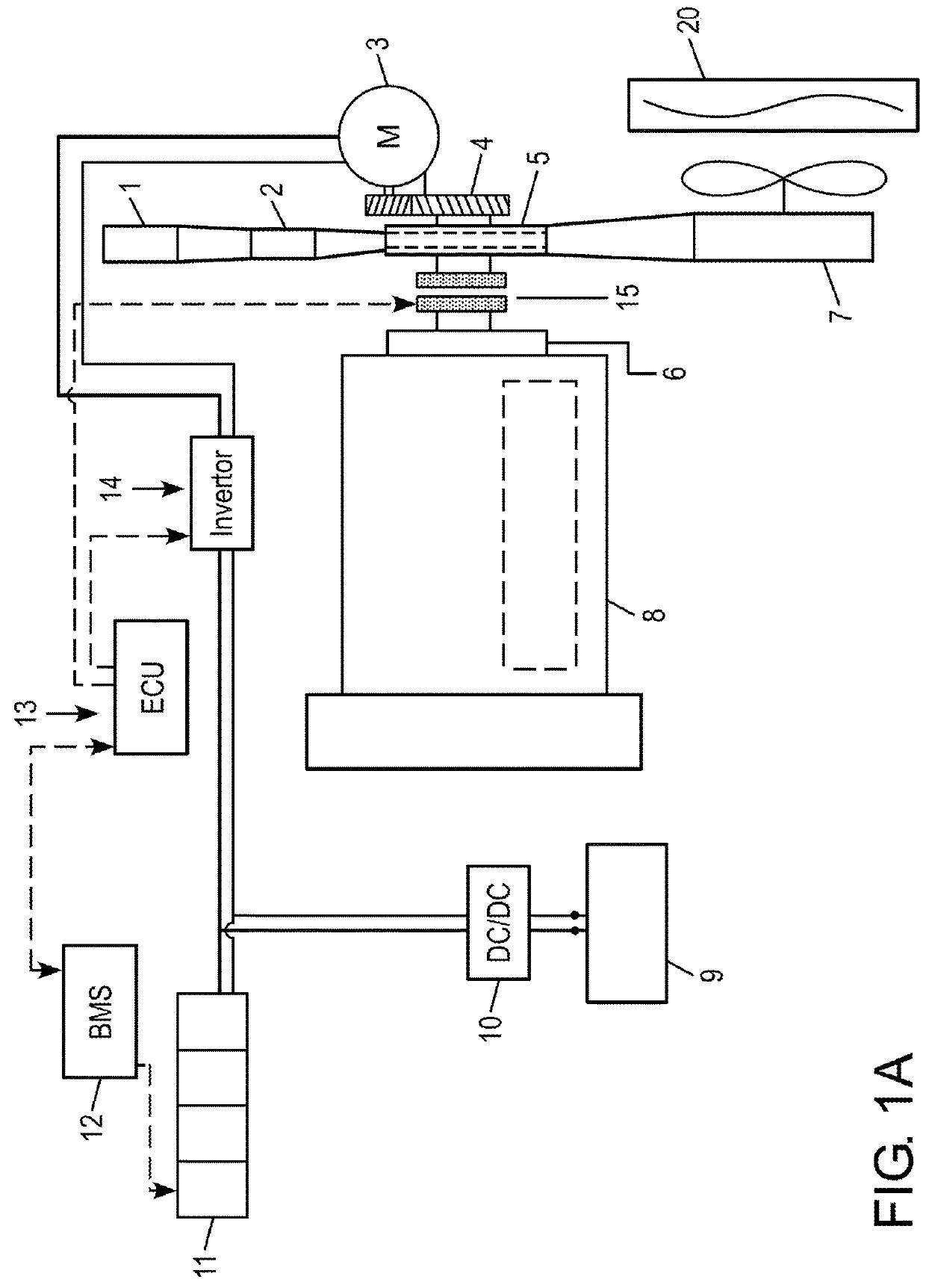
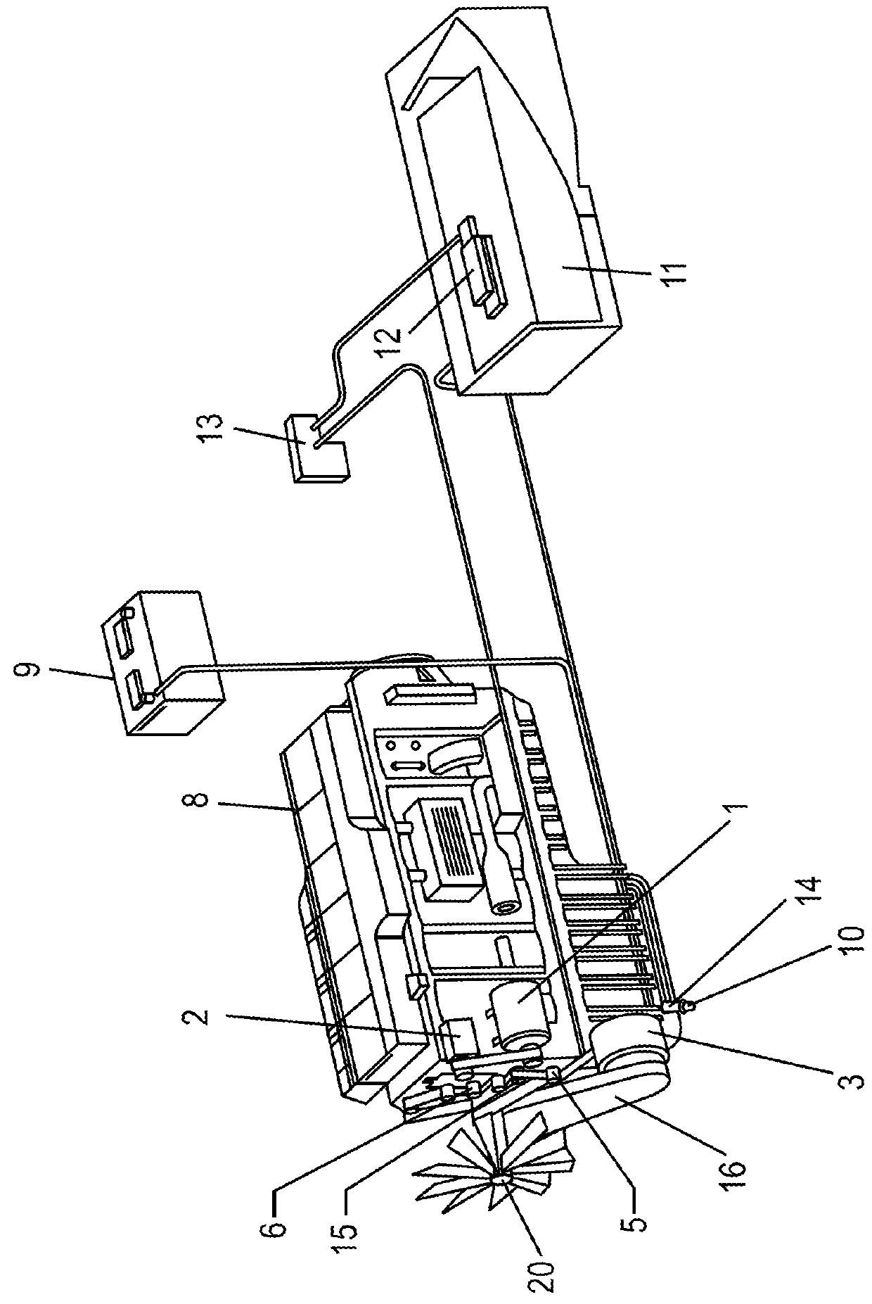
[0086]FIG. 1A is a schematic illustration showing components of an embodiment of an FEMG system in accordance with the present invention. FIG. 1B is a schematic illustration of several of the FEMG system components in the chassis of a commercial vehicle. In this arrangement, the engine accessories (including air compressor 1, air conditioning compressor 2 and engine cooling fan 7 arranged to pull cooling air through engine coolant radiator 20) are belt-driven from a pulley 5. The pulley 5 is located co-axially with a damper 6 coupled directly to the crankshaft of the internal combustion engine 8. The accessories may be directly driven by the drive belt or provided with their own on / off or variable-speed clutches (not illustrated) which permit partial or total disengagement of an individually clutch-equipped accessory from the belt drive.

[0087]In addition to driving the accessory drive belt, the p...


PUM


Abstract

A system and method are provided for hybrid electric internal combustion engine applications in which a motor-generator, a narrow switchable coupling and a torque transfer unit therebetween are arranged and positioned in the constrained environment at the front of an engine in applications such as commercial vehicles, off-road vehicles and stationary engine installations. The motor-generator is preferably positioned laterally offset from the switchable coupling, which is co-axially-arranged with the front end of the engine crankshaft. The switchable coupling is an integrated unit in which a crankshaft vibration damper, an engine accessory drive pulley and a disengageable clutch overlap such that the axial depth of the clutch-pulley-damper unit is nearly the same as a conventional belt drive pulley and engine damper. The front end motor-generator system includes an electrical energy store that receives electrical energy generated by the motor-generator when the coupling is engaged. When the coupling is disengaged, the motor-generator may drive the pulley portion of the clutch-pulley-damper to drive the engine accessories using energy returned from the energy store, independent of the engine crankshaft.

Description

BACKGROUND OF THE INVENTION[0001]The present invention relates to hybrid electric vehicles, and in particular to a system for selective coupling of a hybrid electric generating and storage system with an internal combustion engine. The present invention further relates to a method of operating the system.BACKGROUND OF THE INVENTION[0002]Hybrid electric vehicles having an internal combustion engine combined with a motor-generator and an electrical energy storage system have been the focus of considerable attention in the automotive field, particularly in the field of passenger vehicles. Development of hybrid electric vehicle systems has only recently begun to attract significant interest in commercial and off-road vehicles, e.g., trucks and busses in Vehicle Classes 2-8, in earth-moving equipment and railroad applications, and in stationary internal combustion engine-powered installations.[0003]Hybrid electric technologies offer numerous advantages, including improvements in fuel eff...

Claims


Application Information

Patent Timeline
IPC IPC(8): B60W20/13B60W20/40B60W50/00B60L11/18B60L11/14B60K6/387B60K6/442B60K6/40B60L50/16
CPCB60W20/13B60L2210/10B60W50/0098B60L11/1861B60L11/14B60K6/387B60K6/442B60K6/40B60W2710/0688B60W2710/30B60W2710/182B60W2710/021B60W2710/0666B60W2510/244B60L2240/44B60L2240/42B60L2240/507B60Y2300/91B60Y2400/112B60Y2400/421Y10S903/93B60Y2400/61B60W20/40B60K6/48B60L7/22B60L15/2054B60L2210/42B60L2240/421B60L2240/423B60L2240/441B60L2240/443B60L50/15B60L50/16B60L50/30B60L58/22B60L58/20B60L58/15Y02T10/62Y02T10/64Y02T10/72Y02T10/70Y02T10/7072
Inventor COLAVINCENZO, DAVIDVENEGAS DIAZ, FERNANDO
Owner BENDIX COMML VEHICLE SYST LLC
Why Eureka
Try Eureka