Lock-up device for torque converter

a torque converter and locking device technology, applied in the direction of gearing control, gearing elements, gearing, etc., can solve the problems of affecting the stability of the hydraulic pressure, the inability to obtain desired hydraulic pressure, and the inability to cancel the internal pressure and centrifugal hydraulic pressure, etc., to achieve the effect of stabilizing the hydraulic pressur

Inactive Publication Date: 2018-06-14
EXEDY CORP
View PDF7 Cites 5 Cited by
  • Summary
  • Abstract
  • Description
  • Claims
  • Application Information

AI Technical Summary

Benefits of technology

[0016]According to the present disclosure described above, a lock-up device including a cancellation oil chamber is enabled to stably maintain the hydraulic pressure in the cancellation oil chamber at a desired pressure.

Problems solved by technology

However, the communication hole with a small diameter is likely to be clogged with a foreign object and / or so forth.
Hence, when the communication hole is clogged, the cancellation oil chamber inevitably runs out of the hydraulic oil and a desired hydraulic pressure cannot be obtained therein.
Additionally, when the desired hydraulic pressure cannot be obtained in the cancellation oil chamber, cancellation of the internal pressure and that of the centrifugal hydraulic pressure are disabled.

Method used


Image

  • Lock-up device for torque converter
  • Lock-up device for torque converter
  • Lock-up device for torque converter

Examples


Embodiment Construction

[0025][Entire Configuration of Torque Converter]

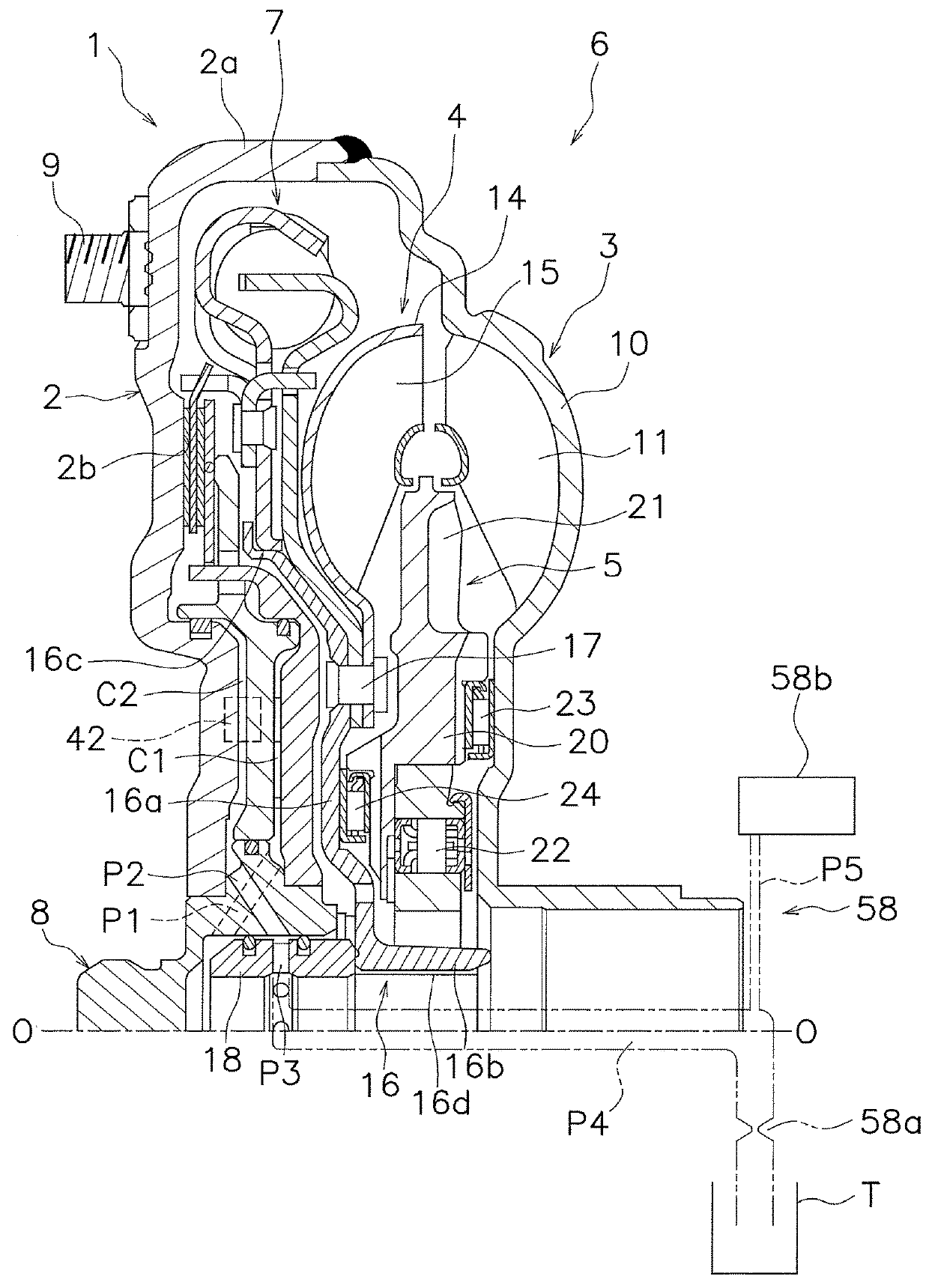
[0026]FIG. 1 is a vertical cross-sectional view of a torque converter 1 employing an exemplary embodiment of the present disclosure. The torque converter 1 is a device that transmits a torque from a crankshaft of an engine to an input shaft of a transmission. In FIG. 1, the engine (not shown in the drawing) is disposed on the left side, whereas the transmission (not shown in the drawing) is disposed on the right side. Line O-O depicted in FIG. 1 is a rotational axis of the torque converter 1.

[0027]The torque converter 1 mainly includes a front cover 2, a torque converter body 6 composed of three types of bladed wheels (an impeller 3, a turbine 4 and a stator 5) and a lock-up device 7.

[0028][Front Cover 2]

[0029]The front cover 2 is a disc-shaped member and a center boss 8 is fixed to the inner peripheral end of the front cover 2 by welding. The center boss 8 is a columnar member extending axially toward the engine, and is inserted into ...


PUM


Abstract

A lock-up device for a torque converter includes a clutch part, a piston, a lock-up oil chamber, a cancellation oil chamber and a cancellation hydraulic pressure maintenance circuit. The clutch part is disposed in a power transmission path between a front cover and a transmission-side member. The piston is provided to be movable in an axial direction. The lock-up oil chamber is supplied with hydraulic oil for moving the piston to turn the clutch part into a power transmission activated state. The cancellation oil chamber is provided on the opposite side of the lock-up oil chamber through the piston, and is supplied with the hydraulic oil. The cancellation hydraulic pressure maintenance circuit is provided in an oil passage for leading the hydraulic oil discharged from the cancellation oil chamber to the transmission side, and maintains the cancellation oil chamber at a predetermined hydraulic pressure.

Description

CROSS-REFERENCES TO RELATED APPLICATIONS[0001]This application is the U.S. National Phase of PCT International Application No. PCT / JP2016 / 071238, filed on Jul. 20, 2016. That application claims priority to Japanese Patent Application No. 2015-161941, filed on Aug. 19, 2015, and Japanese Patent Application No. 2016-059035, filed on Mar. 23, 2016. The contents of all three applications are herein incorporated by reference in their entirety.BACKGROUNDTechnical Field[0002]The present disclosure relates to a lock-up device, and particularly to a lock-up device for a torque converter, which transmits a torque from a front cover to a transmission-side member.Background Art[0003]Torque converters are often equipped with a lock-up device that directly transmits a torque from a front cover to a turbine. The lock-up device includes a clutch part disposed between the front cover and the turbine and a piston that is axially movable. Additionally, moving the piston by hydraulic pressure enables t...

Claims


Application Information

Patent Timeline
Patent Type & Authority Applications(United States)
IPC IPC(8): F16H45/02F16H41/24F16H61/14
CPCF16H45/02F16H41/24F16H61/14F16H2045/0273F16H2041/246F16H2045/0215F16H2045/0221F16H2045/0294F16H2045/0205
Inventor SATO, KEIJI
Owner EXEDY CORP
Why Eureka
Try Eureka