Geothermal power plant utilizing hot geothermal fluid in a cascade heat recovery apparatus

a geothermal power plant and cascade heat recovery technology, applied in steam engine plants, geothermal energy generation, machines/engines, etc., can solve the problems of limited use, inefficient in some applications, and not fully utilizing brine heat, so as to maximize heat extraction from brine and less optimized system

Inactive Publication Date: 2012-12-27
TAS ENERGY
View PDF11 Cites 7 Cited by
  • Summary
  • Abstract
  • Description
  • Claims
  • Application Information

AI Technical Summary

Benefits of technology

[0005]The present invention improves upon the prior art by allowing a more efficient means of using heat release curves from the separated steam and hot brine streams, thereby minimizing the need for multiple ORC systems and the number of heat exchangers through which the steam and hot brine must flow. More specifically, the present invention is generally directed to an improved method for recovering heat from a combined steam / hot brine resource by separating the steam from the hot brine and then utilizing the steam first to drive a steam turbine and then, utilizing the steam turbine exhaust, to provide heat to the working fluid vaporizer heat exchanger, which vaporizer is preferably sized to absorb enough heat from the steam turbine exhaust that the cooled steam condensate leaving the vaporizer may be returned to the ground without having to pass through any additional heat exchangers. The separated hot brine is utilized first to provide heat to the superheater through which vaporized working fluid passes and then to provide additional heat to the working fluid preheater, both of which are preferably sized so as to maximize heat extraction from the brine before the subcooled brine from the preheater is returned to the ground. Because the preheater extracts such a large amount of the remaining usable heat, the subcooled brine can be directly injected into the ground without the need to pass the brine through additional heat exchangers. Preferably, the vaporizer is sized to utilize most of the remaining heat in the steam condensate, such that there is no need to pass this steam condensate leaving the vaporizer though any additional heat exchangers. The condensed steam from the vaporizer may be mixed with the subcooled brine leaving the preheater and this mixed fluid stream may then be reinjected back into the reservoir to maintain hydraulic pressure. An important aspect of the invention is that the sizing of the heat exchangers, as well as the arrangement of the sequence of flow of all three fluids (separated brine, separated steam, and working fluid) must be accomplished in such a way that the heat from the geothermal liquid, as well as the heat contained in the separated steam, are utilized to closely match the heat release curve of the working fluid as discussed below. An additional advantage of using all of the steam condensate heat in a single heat exchanger, i.e., the vaporizer, rather than combining this condensate with the separated brine (to then flow as a combined stream through other heat exchangers) is that combining the streams would require equivalent pressure for both the steam condensate and brine, which requirement would restrict the operating conditions available to those two streams and result in a less optimized system.

Problems solved by technology

More recently there has been limited use of a combined cycle approach, whereby the separated incoming hot brine is used to provide heat to a superheater of an ORC system before being returned back to the ground, while the steam is used in a conventional steam turbine.
One drawback to the systems of the prior art is that they are inefficient in some applications in that they do not fully utilize the brine heat, particularly in geothermal fields where a significant amount of the extracted fluid's heat is contained in the brine.
In other words, the prior art systems are more useful for “steam dominant” resources but are less effective in geothermal fields where a greater portion of the heat may be carried by the brine.
For “brine dominant” resources, the prior art utilized ORC systems without a steam turbine topping cycle or the prior art utilizes more complex ORC designs such as multiple ORC systems or additional heat exchangers, thereby requiring more equipment and expense.

Method used


Image

  • Geothermal power plant utilizing hot geothermal fluid in a cascade heat recovery apparatus
  • Geothermal power plant utilizing hot geothermal fluid in a cascade heat recovery apparatus
  • Geothermal power plant utilizing hot geothermal fluid in a cascade heat recovery apparatus

Examples


Embodiment Construction

[0010]According to Carnot Cycle theory, whenever there is a heat Q transferred from the hot temperature Th reservoir to cold temperature Tc reservoir, the Exergy E, the available energy that can be converted into power rather than heat, is defined by the following formula:

E=Q×(1-TcTh)Equation1

[0011]If the cold reservoir is at atmosphere temperature T0, the hot reservoir temperature is T1, and Exergy is E1, then the formula becomes:

E1=Q×(1-T0T1)Equation2

[0012]Similarly, when heat Q is transferred from T2 (lower than T1) to T0 then,

E2=Q×(1-T0T2)Equation3

[0013]Then during the heat transfer process from T1 to T2, an Exergy loss occurs.

Eloss=E1-E2=Q×(1-T0T1)-Q×(1-T0T2)=Q×T0×T1-T2T1×T2Equation4

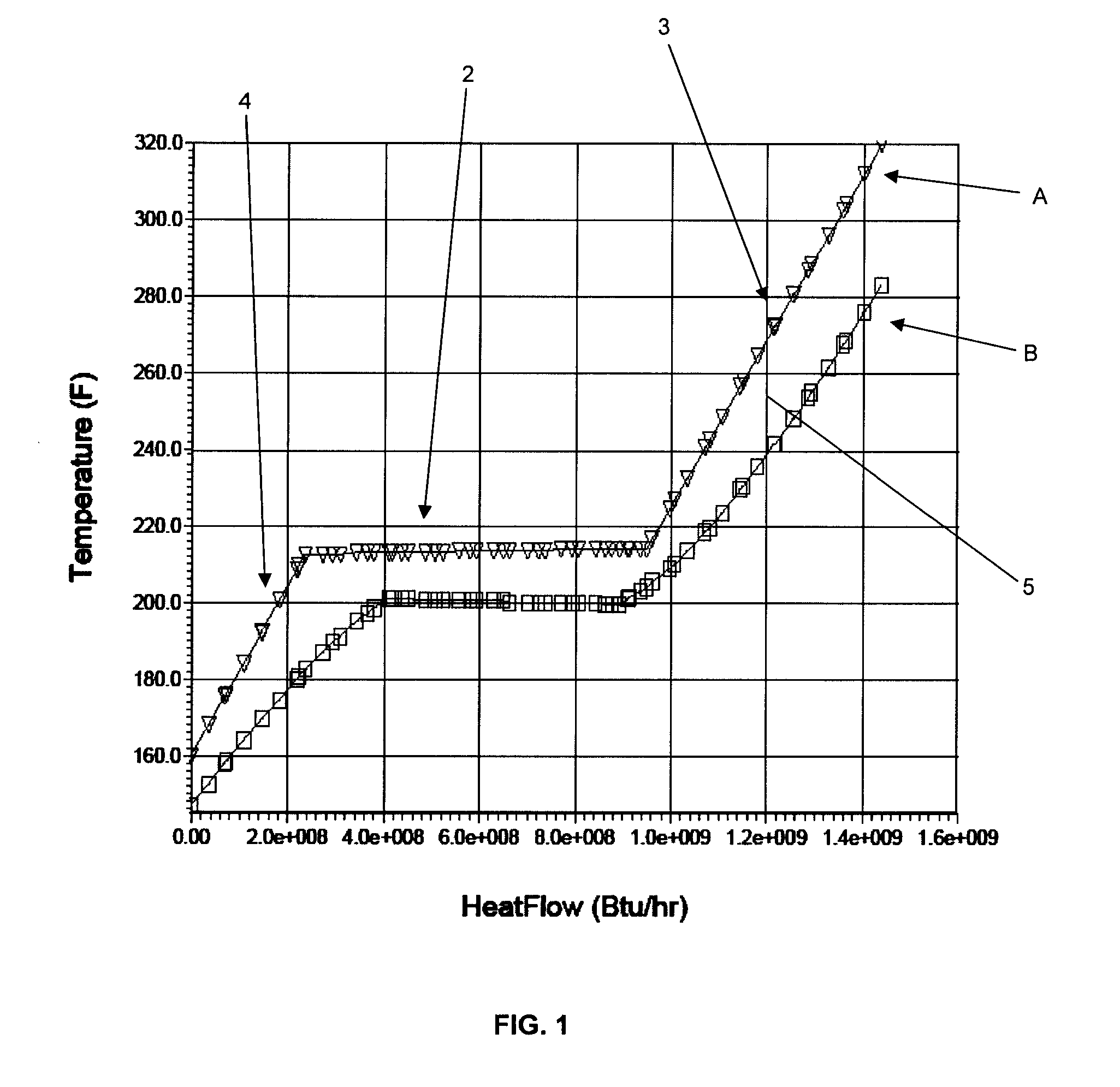
[0014]Based on the foregoing, it is clear that exergy loss is proportional to the temperature difference between the two heat transfer fluids. This suggests it is preferable to design a process where the heat exchanger system employs a tight approach throughout the temperature range to minimize the ...


PUM


Abstract

A geothermal power system includes a steam turbine and a closed loop working fluid system having a preheater, a vaporizer, a superheater, an expander, a condenser, and a pump and a working fluid disposed to pass sequentially through the preheater, vaporizer, superheater, expander, condenser, and pump. Geothermal fluid is separated into a steam stream and a brine stream. The steam is expanded across the steam turbine to generate power, and thereafter exhaust from the steam turbine passes through the vaporizer to vaporize the working fluid. Geothermal brine is first used to heat vaporized working fluid in the superheater and is then used to preheat liquid working fluid in the preheater.

Description

BACKGROUND OF THE INVENTION[0001]1. Field of the Invention[0002]The present invention generally relates to an apparatus and method for producing power using geothermal fluid in an Organic Rankin Cycle (“ORC”) system, and more particularly, to an apparatus and method to optimize heat release from brine extracted from a geothermal reservoir and minimize the ORC system equipment.[0003]2. Description of the Related Art[0004]In general, there is a constant drive to increase the operating efficiency of geothermal power plants. Geothermal fluid recovered from a geothermal reservoir typically contains a mixture of steam and hot liquid. The liquid is often in the form of brine. In many high temperature brine geothermal fields, the prior art practice has been to flash the steam at a lower pressure and separate the geothermal steam from the geothermal brine and utilize the steam in a steam turbine power system. Specifically, power was produced by using the steam in a traditional steam turbine ...

Claims


Application Information

Patent Timeline
Patent Type & Authority Applications(United States)
IPC IPC(8): F03G7/00F01K23/06F01K7/34
CPCF01K25/10Y02E10/10F03G7/04F24T10/20
Inventor PIERSON, THOMAS L.CHEN, GUOFU
Owner TAS ENERGY
Why Eureka
Try Eureka