Venturi muffler

Inactive Publication Date: 2009-12-17
SULLIVAN JOHN T
View PDF19 Cites 15 Cited by
  • Summary
  • Abstract
  • Description
  • Claims
  • Application Information

AI Technical Summary

Benefits of technology

[0010]The venturi muffler of the invention further acts as a heat sink to remove heat from the engine exhaust as it passes therethrough and converts the heat into thermo-electrical power. Each of the venturi-forming segments and specifically each of the outermost cylindrical walls thereof form the exterior of the muffler or are in intimate surface-to-surface contact with an exterior outermost metallic sleeve. Thermo-electric modules are connected to the outermost annular walls of the segments or to the outermost metallic sleeve and the heat of the exhaust gasses which is extracted by each of the segments is conducted therethrough to the outermost annular walls of each segment and / or to the cylindrical outermost sleeve, wall or casing surrounding the same to which are connected thermal-electric modules for converting the exterior normally wasted heat to electrical power. Additionally, when heat is removed from the exhaust, energy is removed and the sound / noise of the exhaust is further lowered. The partial vacuum created by the exhaust gasses passing between inner and outer surfaces of the conical outlet walls of each venturi-forming segments also draws the hot exhaust gasses across the surfaces of both sides of each conical wall outlet to maximize heat extraction from the exhaust gasses and conduct the same to the exterior of the muffler.
[0011]In further accordance with the invention, the annular series of holes in the outermost and innermost annular walls of the segments also break up the sound waves into smaller Eddie currents which reduce sound as sound waves are introduced into each annular chamber causing reflection thereof progressively from the muffler inlet to the muffler outlet which dissipates sound energy without robbing engine power and saving fuel by lowering engine back pressure while at the same time converting normally wasted heat into thermo-electric power. Each venturi muffler can be “tuned” by varying the number of venturi-forming segments to efficiently dampen or attenuate the specific frequencies which are desired to be cancelled out of incoming sound waves. The venturi muffler can be further “tuned” by varying the size and number of the holes in the innermost and / or outermost annular walls, the axial length of the peripheral walls which varies the axial length of the innermost and / or outermost chambers and the length, angle of convergence and discharge opening of each of the conical venturi-forming walls.

Problems solved by technology

Internal combustion engines create noise which is generated by the sudden expansion of internal combustion engine chamber exhaust gasses.

Method used


Image

  • Venturi muffler
  • Venturi muffler
  • Venturi muffler

Examples


Embodiment Construction

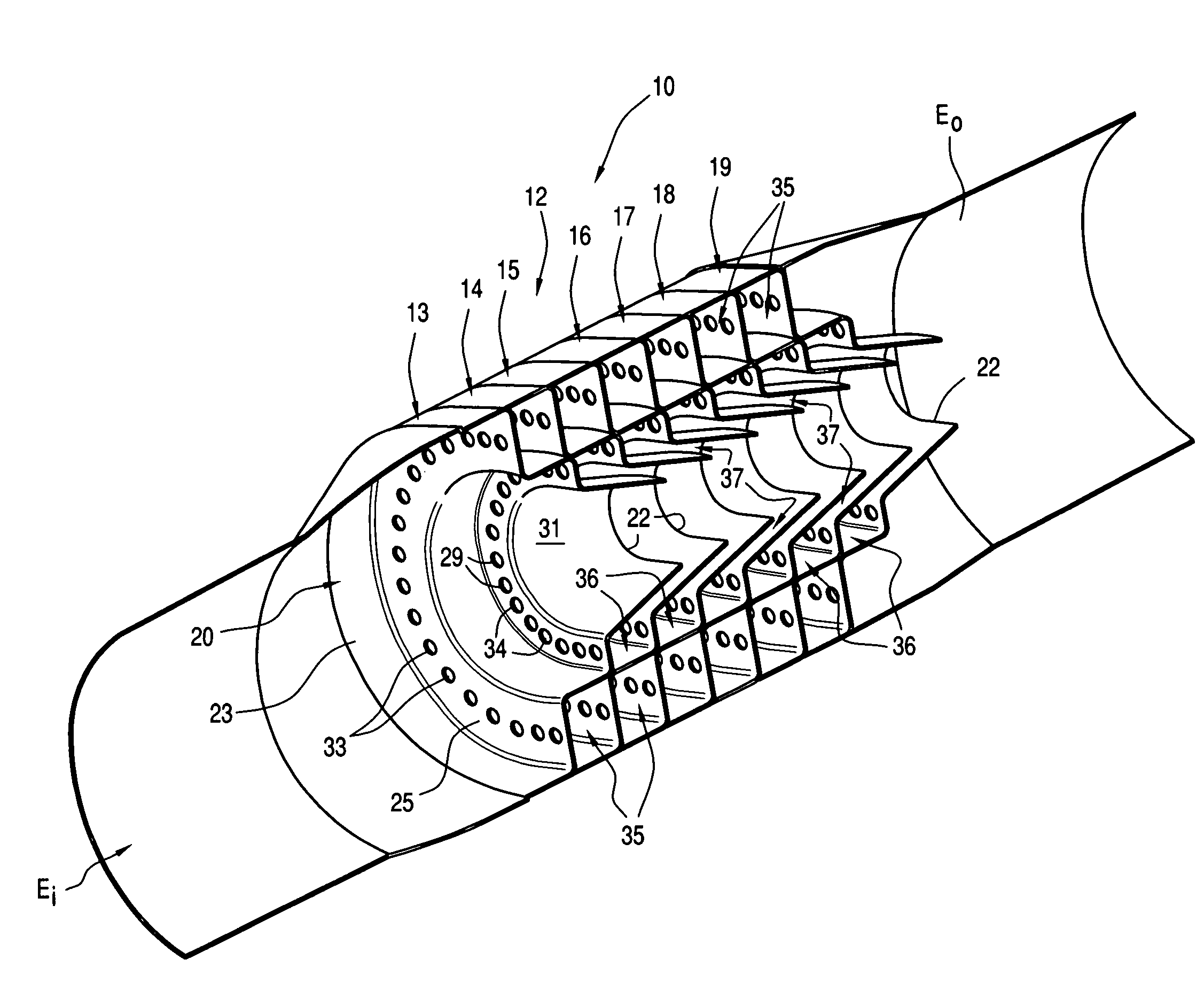
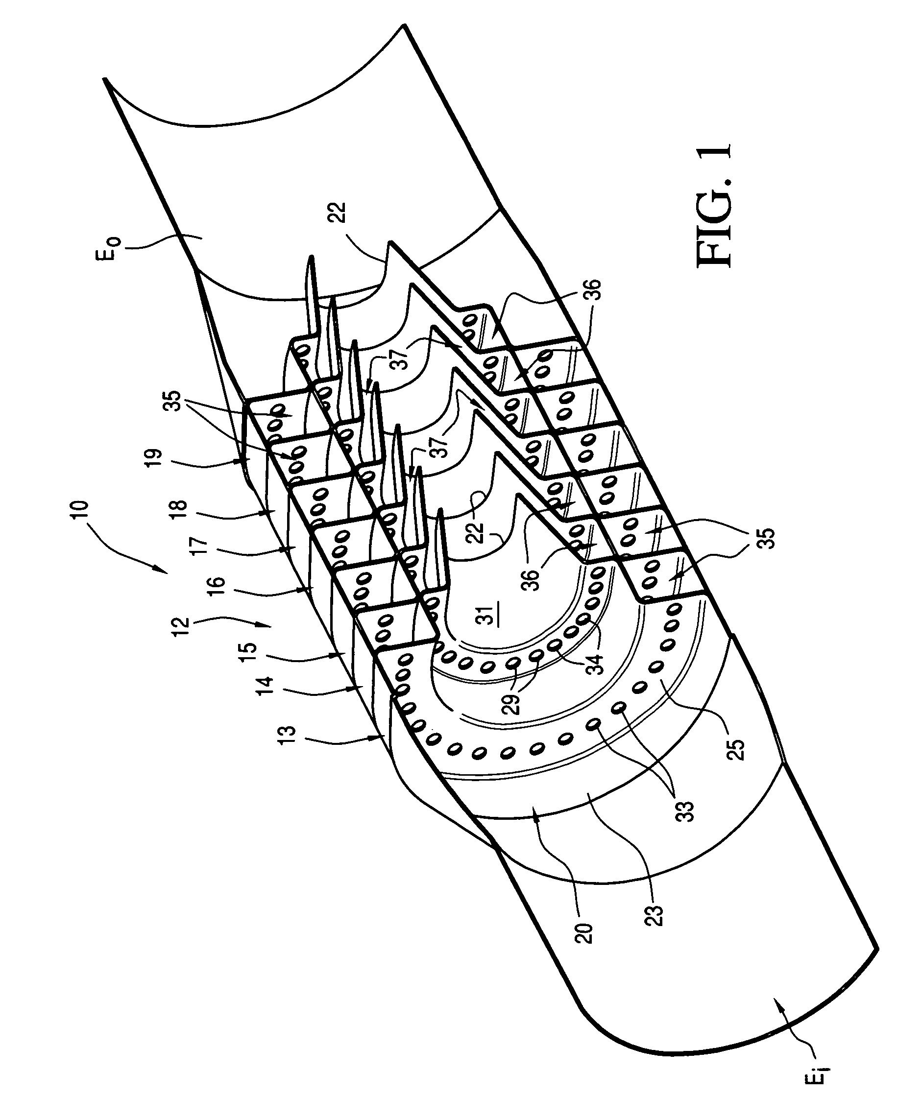
[0032]A venturi muffler constructed in accordance with this invention is fully illustrated in FIG. 1 of the drawings and is generally designated by the reference numeral 10. The venturi muffler 10 includes an exhaust inlet Ei, an exhaust outlet Eo, and therebetween a medial sound damping or sound attenuating section 12 which dampens, reduces, attenuates or muffles the noise caused by the sudden expansion of internal combustion chamber exhaust gasses of a conventional internal combustion engine (not shown) connected to the exhaust inlet Ei.

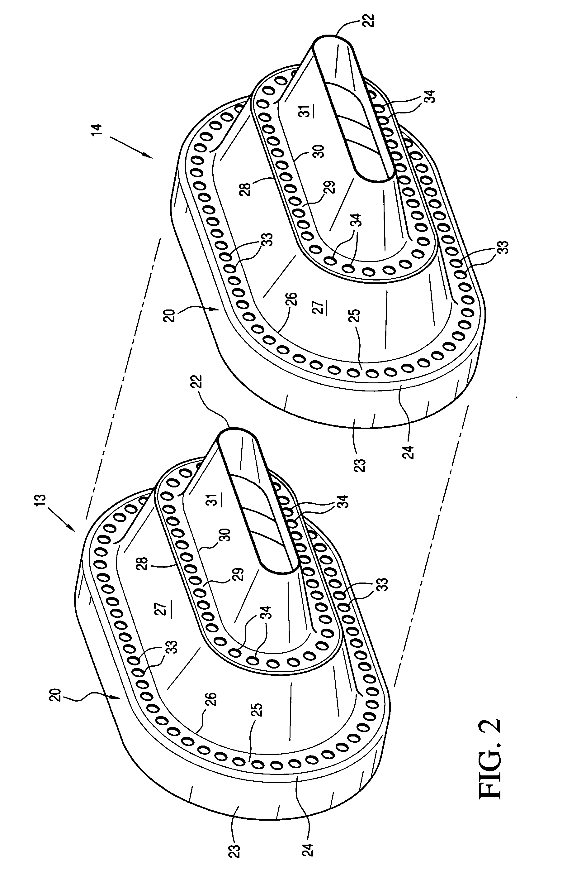
[0033]The sound damping section 12 is, for illustrative purposes, formed by seven vacuum or partial vacuum-forming / venturi-forming segments 13 through 19, though more or less such venturi-forming segments may be utilized depending upon the particular application. The venturi-forming segments 13 and 14 of FIGS. 1 through 3 will be described in detail and the description thereof is equally applicable to the remaining venturi-forming segments 15 throu...


PUM


Abstract

A venturi muffler is made of a plurality of metallic tubular stepped members which are stacked together and define at least one sound-reflective chamber which opens through an annular venturi passage into an axial flow passage of the venturi muffler thereby creating a partial vacuum in the annular chamber. The annular chambers include aligned openings through which exhaust gasses flow but are also reflected by walls of the sound-reflective chambers. Therefore, the exhaust sound or noise is dampened by the cancellation of sound waves 180 degrees out of phase with each other, the creation of a partial vacuum through which sound cannot propagate or propagates minimally, and by the heat removed by all of the metallic heat-conductive venturi-forming segments of the venturi muffler.

Description

FIELD OF THE INVENTION[0001]The present invention relates to mufflers for internal combustion engines.BACKGROUND OF THE INVENTION[0002]Internal combustion engines create noise which is generated by the sudden expansion of internal combustion engine chamber exhaust gasses. As the combustion gasses are exhausted from each cylinder of the engine, a sound wave front travels at rapid sonic velocities through the exhaust system. Efforts have continued over many years to reduce or muffle the noise caused by combustion gasses.[0003]U.S. Pat. No. 5,952,625 granted on Sep. 14, 1999 to Ronald G. Huff describes two major muffler classifications, namely, dissipative and reactive mufflers. Dissipative mufflers are typically composed of ducts or chambers filled with acoustic materials, such as fiberglass, steel wool or porous ceramics. Such materials absorb acoustic energy and transform it into thermal energy. Reactive mufflers are composed of a number of interconnected chambers of various sizes a...

Claims


Application Information

Patent Timeline
IPC IPC(8): F01N1/00
CPCF01N1/003F01N1/06F01N1/083F01N2470/30F01N2470/02F01N2470/24F01N1/086
Inventor SULLIVAN, JOHN T.
Owner SULLIVAN JOHN T
Why Eureka
Try Eureka