
Enabling system for an implement controller

a technology of implement controller and enablement system, which is applied in the field of work vehicles, can solve the problems of non-ideal enablement, insufficient assurance of the backhoe tool,

Active Publication Date: 2005-10-06
DEERE & CO
View PDF13 Cites 8 Cited by
  • Summary
  • Abstract
  • Description
  • Claims
  • Application Information

AI Technical Summary

Benefits of technology

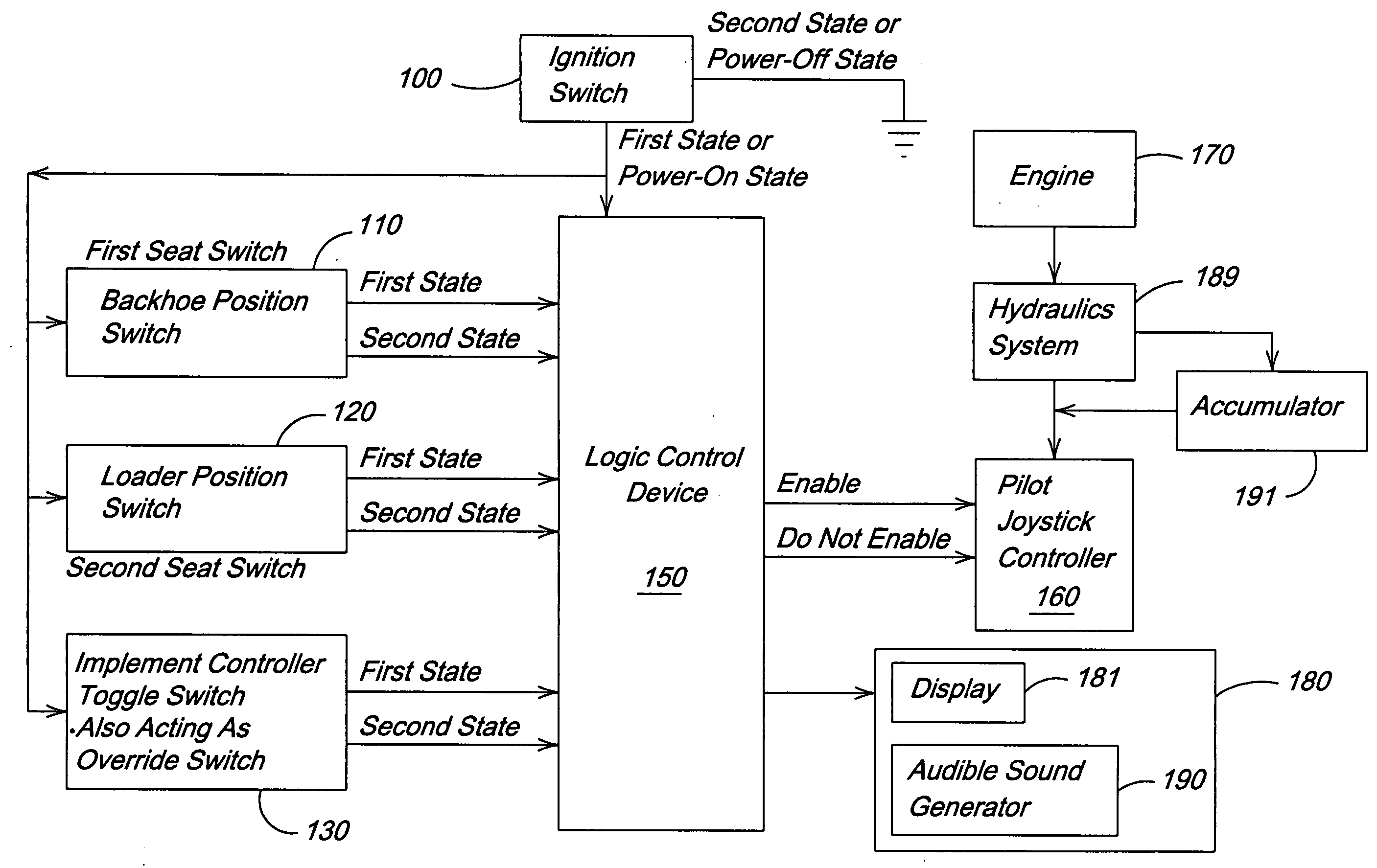
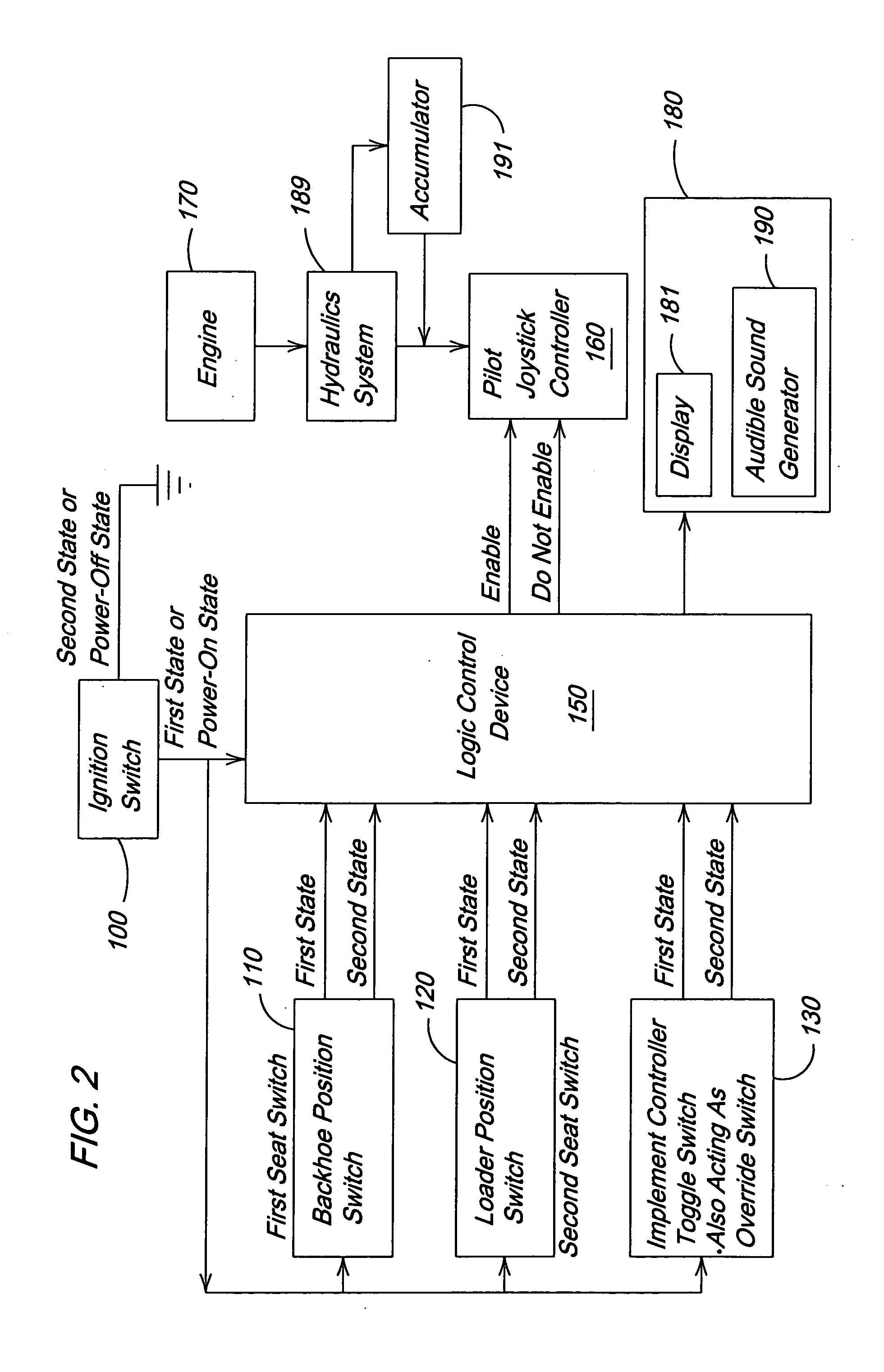
[0008] The enabling system achieves the best results when the vehicle is functioning properly but may be required during a malfunction of the vehicle. Thus, an option is provided in which an accumulator maintains backup hydraulic pressure for the backhoe functions allowing the operator to lower the backhoe instrument to the ground in a controlled fashion should the engine stop or fail.

Problems solved by technology

Many modern controllers such as, for example, pilot controllers and electro-hydraulic controllers (hereafter implement controllers) are, by their very nature, easy to manipulate and conventional enablement systems may not provide adequate assurance that the backhoe tool will be manipulated only by deliberate acts of the operator.
Accentuating this problem is the fact that the controller towers on which the implement controllers are usually mounted tend to be relatively close to the seat.
Thus, non-ideal enablement is, in essence, an override condition in which the implement controller toggle switch acts as an override switch.

Method used


Image

  • Enabling system for an implement controller
  • Enabling system for an implement controller
  • Enabling system for an implement controller

Examples


Embodiment Construction

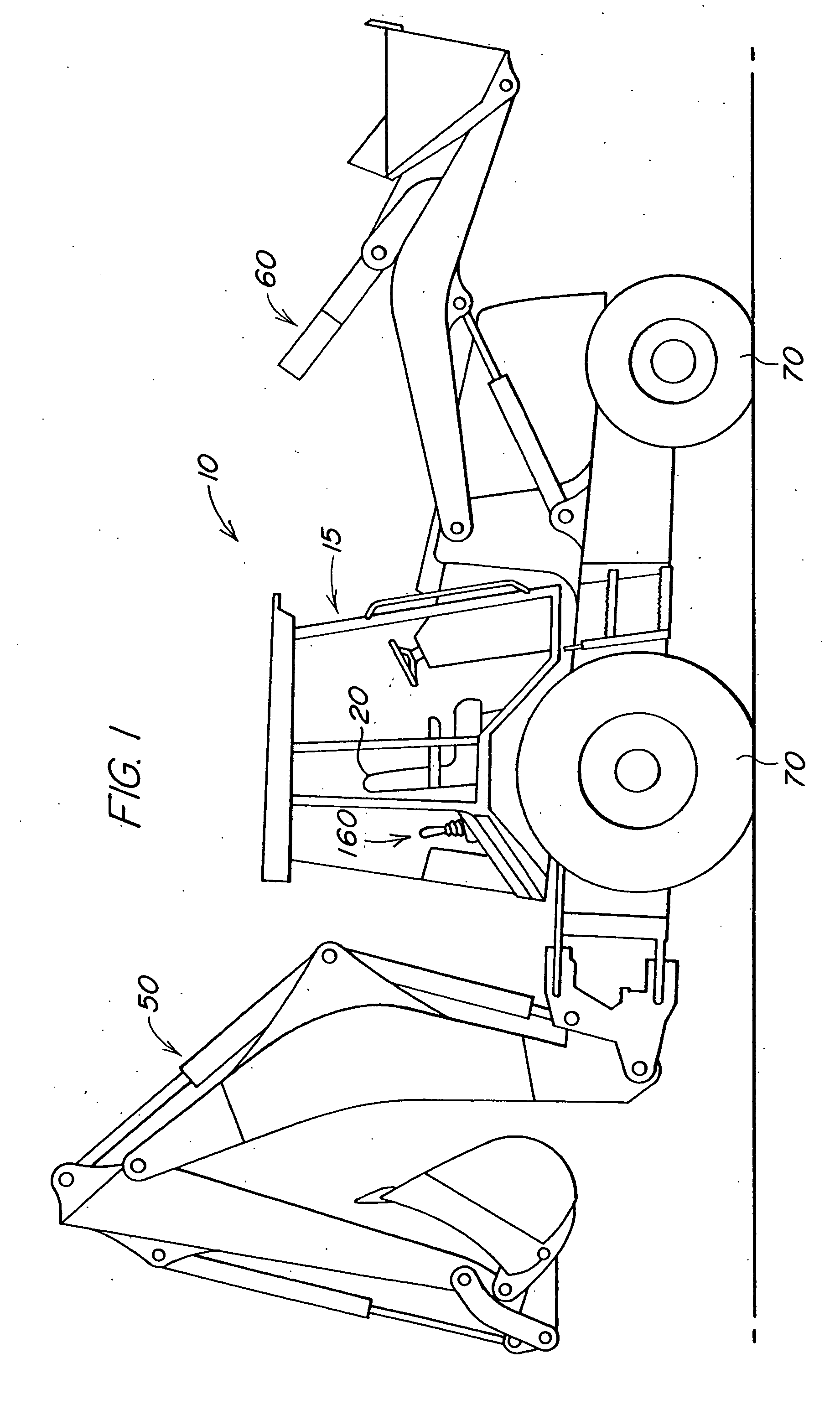
[0014]FIG. 1 illustrates a work vehicle 10 in which the invention may be used. The particular work vehicle 10 shown in FIG. 1 is a loader backhoe which, typically, has dual functions. The functions of the particular work vehicle 10 illustrated are that of a backhoe and that of a loader. The work vehicle 10 includes a cab 15, a swivel seat 20, at least one implement controller 160, a backhoe portion 50 and a loader portion 60. It also includes wheels 70 as well as a propulsion system (not shown) that propels it along the ground in a manner well known in the art. The swivel seat 20 has at least two set positions, i.e., swivel angles at which it can be locked. These set positions include at least an angle in which the swivel seat 20 faces the backhoe portion 50 and an angle in which the swivel seat 20 faces the loader portion 60; they are usually 180° apart angularly as indicated in FIG. 1. The swivel seat 20 is in the backhoe or loader operating position when it is within about 15° of...


PUM


Abstract

The entire right, title and interest in and to this application and all subject matter disclosed and / or claimed therein, including any and all divisions, continuations, reissues, etc., thereof are, effective as of the date of execution of this application, assigned, transferred, sold and set over by the applicant(s) named herein to Deere & Company, a Delaware corporation having offices at Moline, Ill. 61265, U.S.A., together with all rights to file, and to claim priorities in connection with, corresponding patent applications in any and all foreign countries in the name of Deere & Company or otherwise.

Description

FIELD OF THE INVENTION [0001] The invention relates to work vehicles having multiple position swivel seats and implement controllers that are easily operated. More particularly, the invention relates to loader backhoes with easily operated implement controllers. BACKGROUND OF THE INVENTION [0002] Traditional control systems for backhoes have included floor mounted hydraulic levers with a sufficient resistance to movement and an adequate distance from the swivel seat to avoid inadvertent operation. Some have included rudimentary enablement conditions, e.g., an operator's presence switch that detects a weight on the vehicle seat, to activate the traditional controllers. Still others have included systems with pilot controllers that automatically enable and disable the pilot controllers in accordance with seat orientation, i.e., enablement typically requires a seat orientation in the direction of the controls to be enabled. SUMMARY OF THE INVENTION [0003] Many modern controllers such a...

Claims


Application Information

Patent Timeline
Patent Type & Authority Applications(United States)
IPC IPC(8): E02F9/20E02F9/24G06F19/00
CPCE02F9/166E02F3/964E02F9/2012E02F9/24
Inventor MERTEN, JAMES GERALDHACHMANN, ROBERT JOSEPHMUSMAKER, BRUCE ALLANGACIOCH, MICHAEL
Owner DEERE & CO
Learn More