Microscope with friction drives

Inactive Publication Date: 2018-06-14
LEICA MICROSYSTEMS CMS GMBH
View PDF7 Cites 1 Cited by
  • Summary
  • Abstract
  • Description
  • Claims
  • Application Information

AI Technical Summary

Benefits of technology

The invention is about a microscope that is cheap to make and runs smoothly, with low noise and precise positioning of its parts.

Problems solved by technology

Positively engaging force transfer systems of this kind are disadvantageous firstly in that they require very high precision in order to run quietly.
This requires very small tolerances in the context of production and assembly, making the microscopes very expensive to manufacture.
In addition, microscopes having a positively engaging force transfer system always exhibit hysteresis behavior upon a change in the direction of motion, making it more difficult to return precisely to desired positions.
The positively engaging drives are furthermore relatively loud and exhibit poor smoothness.
Positively engaging drives of this kind also must be regularly lubricated, resulting in a recurring maintenance outlay.

Method used


Image

  • Microscope with friction drives
  • Microscope with friction drives
  • Microscope with friction drives

Examples


Embodiment Construction

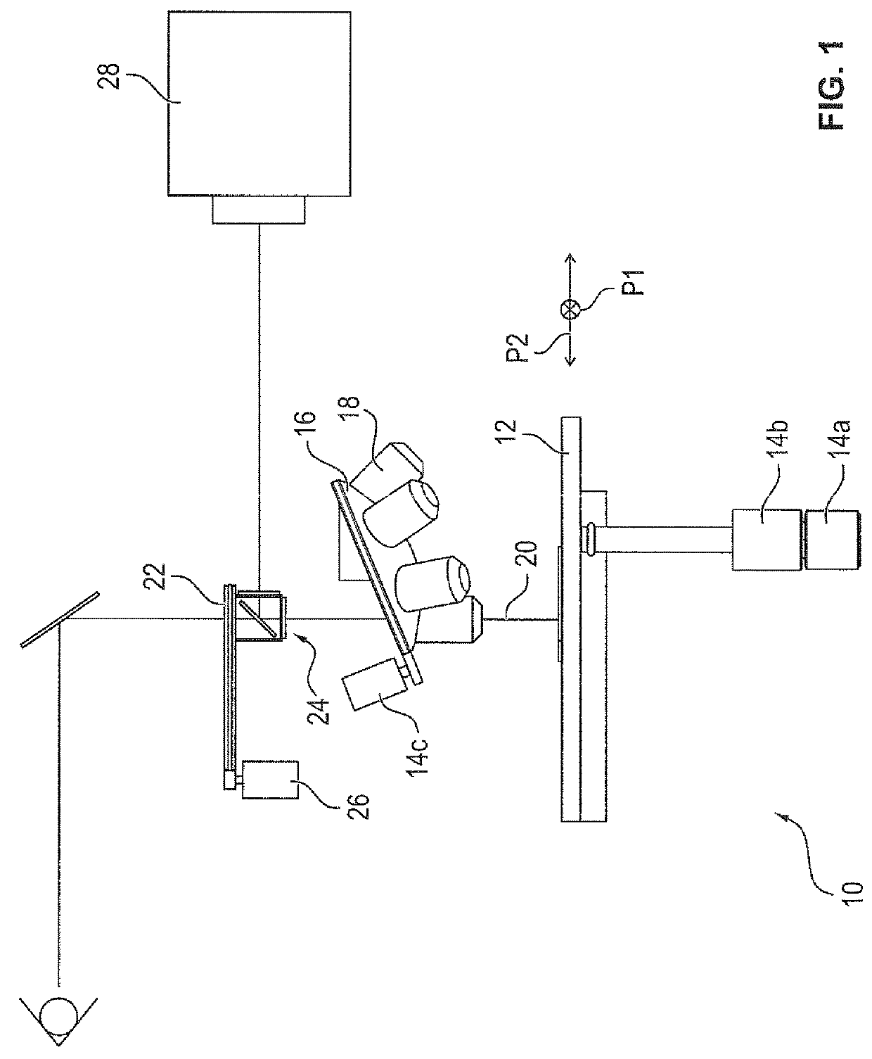
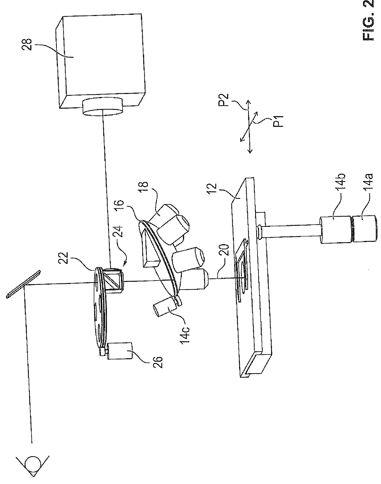
[0040]FIG. 1 is a highly simplified schematic depiction of an upright microscope 10. FIG. 2 is a perspective schematic depiction of microscope 10 according to FIG. 1. Only the relevant functional parts of microscope 10 are respectively shown.

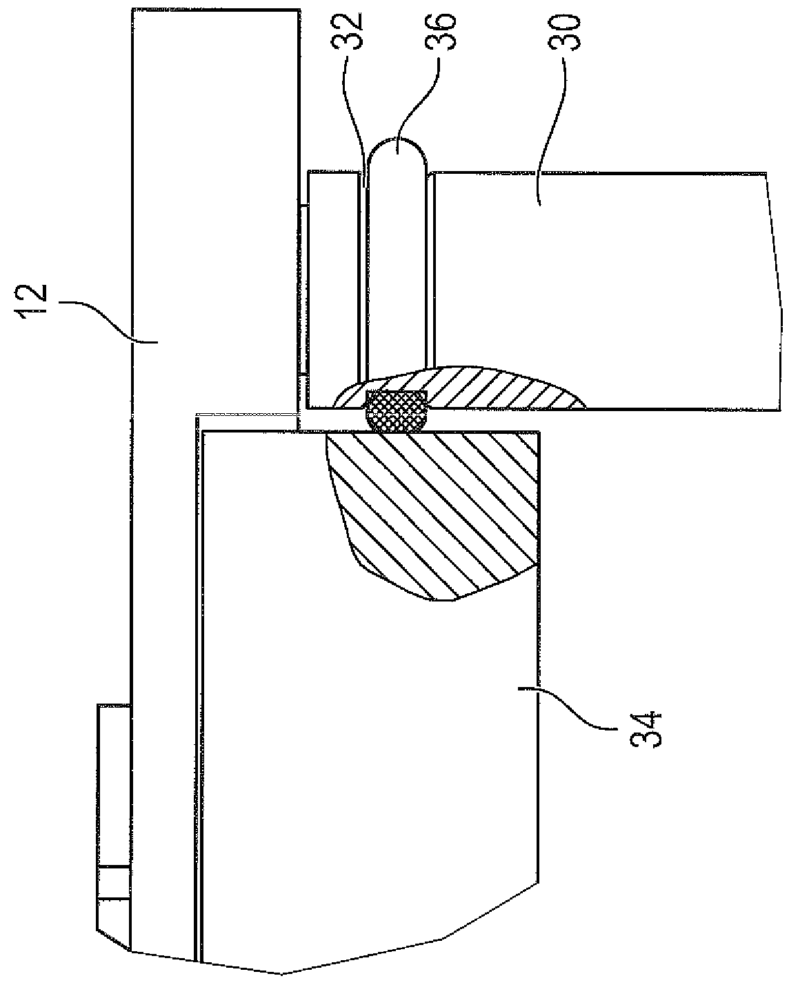
[0041]Microscope 10 comprises a specimen stage 12 on which the specimens to be microscopically examined are mounted. Specimen stage 12 is movable in an X direction, indicated by double arrow P1, with the aid of a drive unit 14. Embodied for this purpose between drive unit 14 and specimen stage 12 is a frictionally engaging connection that will be described later in further detail in conjunction with FIG. 3.

[0042]Microscope 10 furthermore comprises an objective turret 16 that comprises a plurality of objectives, one of which is labeled by way of example with the reference character 18. A different objective 18 is pivoted into beam path 20 of microscope 10 depending on the rotational position of objective turret 16.

[0043]Microscope 10 furthermore ...


PUM


Abstract

The invention relates to a microscope (10, 50) having a specimen stage (12) movable in an X direction and / or a Y direction and having an objective turret (16), the microscope (10, 50) encompassing a first drive unit (14a) with which the specimen stage (12) is movable in the X direction, a second drive unit (14b) with which the specimen stage (12) is movable in the Y direction, and / or a third drive unit (14c) with which the objective turret (16) is rotatable. The connections between the drive units (14a, 14b, 14c) and the specimen stage or the objective turret (16) are respectively embodied as a frictional connection.

Description

CROSS-REFERENCE TO RELATED APPLICATIONS[0001]The present application is the U.S. national phase of International Application No. PCT / EP2016 / 062943 filed Jun. 8, 2016, which claims priority of German Application No. 10 2015 109 149.6 filed Jun. 10, 2015, the entire disclosure of which is incorporated herein by reference.FIELD OF THE INVENTION[0002]The invention relates to a microscope that comprises a specimen stage movable in an X direction and a Y direction, and an objective turret. The microscope furthermore has a first drive unit with the aid of which the specimen stage is movable in the X direction, and a second drive unit with the aid of which the specimen stage is movable in the Y direction. Also provided is a third drive unit with the aid of which the objective turret is rotatable.BACKGROUND OF THE INVENTION[0003]In known microscopes, force and torque are transferred from the drive units to the respective elements to be displaced, i.e. for example the specimen stage or the ob...

Claims


Application Information

Patent Timeline
IPC IPC(8): G02B21/24G02B7/16G02B21/26
CPCG02B21/248G02B7/16G02B21/26G02B21/06
Inventor KUBEK, MARTIN
Owner LEICA MICROSYSTEMS CMS GMBH
Why Eureka
Try Eureka