Camera arrangement with illuminator

a technology of illuminator and camera, which is applied in the field of camera arrangement with illuminator, can solve the problems of affecting the quality of the image, so as to reduce the risk of unwanted reflection

Active Publication Date: 2018-06-14
AXIS
View PDF0 Cites 25 Cited by
  • Summary
  • Abstract
  • Description
  • Claims
  • Application Information

AI Technical Summary

Benefits of technology

[0008]It is an object of the disclosure to provide a camera arrangement comprising a dome and an illumination arrangement, which reduces the risk of unwanted reflections into the image sensors.
[0009]Another object is to provide a camera arrangement in which mounting is simplified, while still ensuring proper isolation of the illumination arrangement.
[0010]These and other objects are achieved, in full or at least in part, by a camera arrangement comprising a camera head, an illumination arrangement and a dome, wherein the camera head is arranged inside the dome, and the illumination arrangement is arranged on an outside of the dome. With such a camera arrangement, it is possible to provide light for monitoring a scene which otherwise contains too little light, while avoiding the risk of internal reflections in the dome. The dome has a toroidal shape with a rotational symmetry along a rotational angle (α) around a first axis of symmetry (S1), at least an outer segment of the dome is transparent, the outer segment has a shape in section which is defined by a second axis of symmetry (S2) arranged at a first radius (R) from the first axis of symmetry (S1) and orthogonal to the first axis (S1), the outer segment having a radius of curvature (r) over an angle (β) around the second axis of symmetry (S2), the dome further comprises a central segment connecting the outer segment with the first axis of symmetry, and the illumination arrangement is arranged at the central segment. A dome of this shape makes it possible to tilt each camera head to a desired angle while still maintaining essentially the same distance from an inside of the outer segment of the dome. Thereby, optical aberrations caused by the dome may be avoided. Further, the central segment provides a suitable location for the illumination arrangement, ensuring that the illumination arrangement does not block the field of view of any of the camera heads. It may be noted that the description of the central segment as connecting the outer segment with the first axis of symmetry, should not be taken literally, as the first axis of symmetry is a geometrical construct, and not necessarily a physical one.

Problems solved by technology

In a well-lit scene, the IR component is generally a disadvantage, as it distorts the colours of captured images compared to what the human eye can see.
A problem with such an arrangement is that there is a risk that light from the illuminator is reflected on the inside of the dome and enters the camera, thereby causing complete or partial saturation of the image sensor.
If the dome is not mounted carefully, stray light from the illuminator may still be reflected and reach the image sensor.
This becomes even more problematic in camera arrangements having more than one camera head, as each camera head has to be sealed off properly.
However, this solution comes at the cost of a less protected camera, making the camera unsuited for applications where there is a risk of, e.g., vandalism.
The problems described above in connection with IR illuminators apply also to visible light illuminators.
Still, there are situations when visible illumination would be annoying, e.g., to neighbours.

Method used


Image

  • Camera arrangement with illuminator
  • Camera arrangement with illuminator
  • Camera arrangement with illuminator

Examples


Embodiment Construction

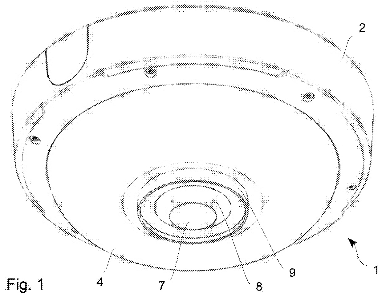
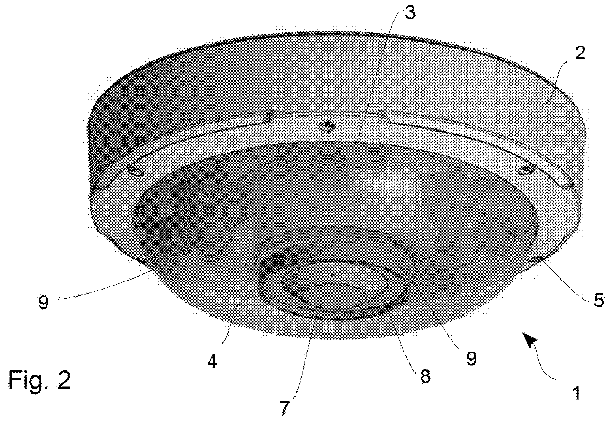
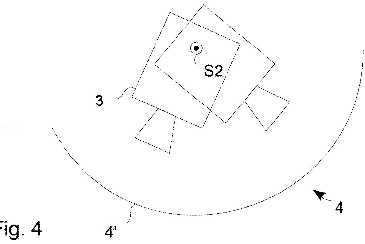
[0028]In FIGS. 1 and 2, a camera arrangement 1 is shown, which has a base 2, four camera heads 3, and a dome 4. For the sake of clarity of other details, the camera heads are not visible in FIG. 1, but three of them may be seen in FIG. 2, the fourth one being obscured at the back in this view. The camera heads 3 are arranged inside the dome 4. The camera heads 3 may be mounted on holders 5 held by magnetic force on a mounting rail (not shown) as disclosed in applicant's EP-2 887 328, which is incorporated herein by reference.

[0029]In FIG. 1, the dome 4 has a toroidal shape, which may be said to be a halved “donut” or a halved “swim ring”, and which is shown separately in FIG. 3. Such a dome is disclosed in applicant's as yet unpublished EP application No. 15194656.3, which is also incorporated herein by reference. The shape of the dome may be described as being toroidal with a rotational symmetry along a rotational angle α around a first axis of symmetry S1. Further, the dome has an...


PUM


Abstract

A camera arrangement comprising a camera head, an illumination arrangement, and a dome. The camera head is arranged inside the dome, and the illumination arrangement is arranged on an outside of the dome.

Description

FIELD OF INVENTION[0001]The present teachings relate to monitoring cameras having integrated illumination arrangements, and in particular monitoring cameras having IR illuminators.BACKGROUND[0002]Monitoring cameras are used in many different applications, both indoors and outdoors, for monitoring a variety of environments. Digital monitoring cameras use image sensors that are sensitive to a wider spectral range of light than the human eye. Digital image sensors, such as CCD sensors and CMOS sensors, are sensitive not only to visual light, but also to part of the IR spectral range. In a well-lit scene, the IR component is generally a disadvantage, as it distorts the colours of captured images compared to what the human eye can see. Therefore, an IR cut filter is normally placed in front of the image sensor in a day-mode of the camera, such that only visual light reaches the image sensor. When there is little visual light in the scene, such as at night, the sensitivity to IR light may...

Claims


Application Information

Patent Timeline
Patent Type & Authority Applications(United States)
IPC IPC(8): G08B13/196G03B17/02H04N5/225
CPCG08B13/19632G03B17/02H04N5/2256H04N5/2252H04N5/2254G08B13/19619F16M13/02H04N7/181H04N23/54H04N23/55H04N23/74H04N23/56H04N23/11H04N23/90H04N23/50H04N7/18H04N23/51G03B17/12G03B17/561
Inventor LARSSONHERTZMAN, ANDREAS
Owner AXIS
Why Eureka
Try Eureka