Flexible electronic device and method for manufacturing flexible electronic device

Inactive Publication Date: 2018-06-14
SHARP KK
View PDF1 Cites 18 Cited by
  • Summary
  • Abstract
  • Description
  • Claims
  • Application Information

AI Technical Summary

Benefits of technology

[0023]According to an aspect of the present invention, it is possible to provide (i) a flexible electronic device and (ii) a method of producing the flexible elec

Problems solved by technology

A flexible electronic device thus has a problem of an advance of a crack which advance is caused by bending of the flexible electronic

Method used


Image

  • Flexible electronic device and method for manufacturing flexible electronic device
  • Flexible electronic device and method for manufacturing flexible electronic device
  • Flexible electronic device and method for manufacturing flexible electronic device

Examples


embodiment 1

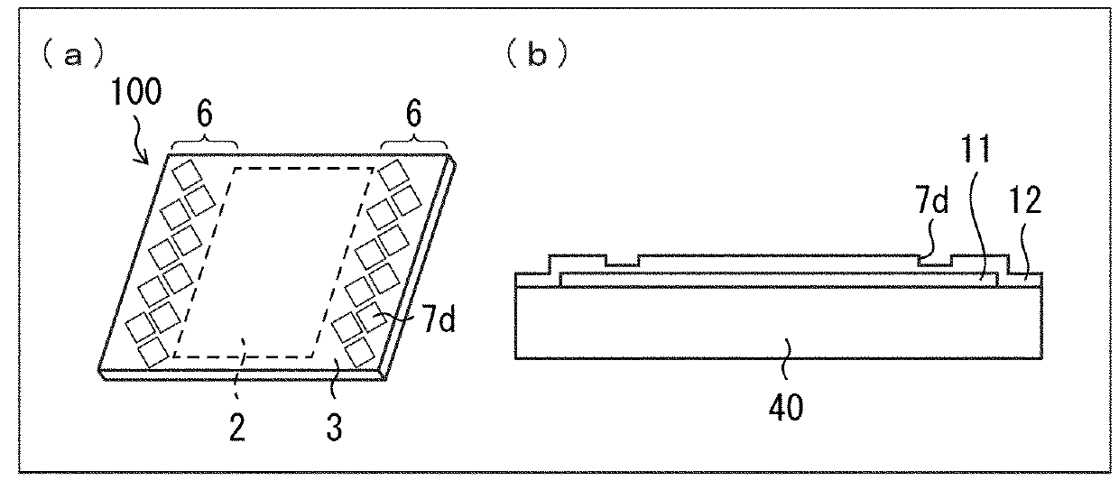
[0031]Embodiment 1 of the present invention will be specifically described below with reference to (a) through (c) of FIG. 1, and (a) and (b) of FIG. 3.

[0032]Note that the following description will take a flexible organic EL display panel as an example of a flexible electronic device in accordance with the present invention.

[0033]

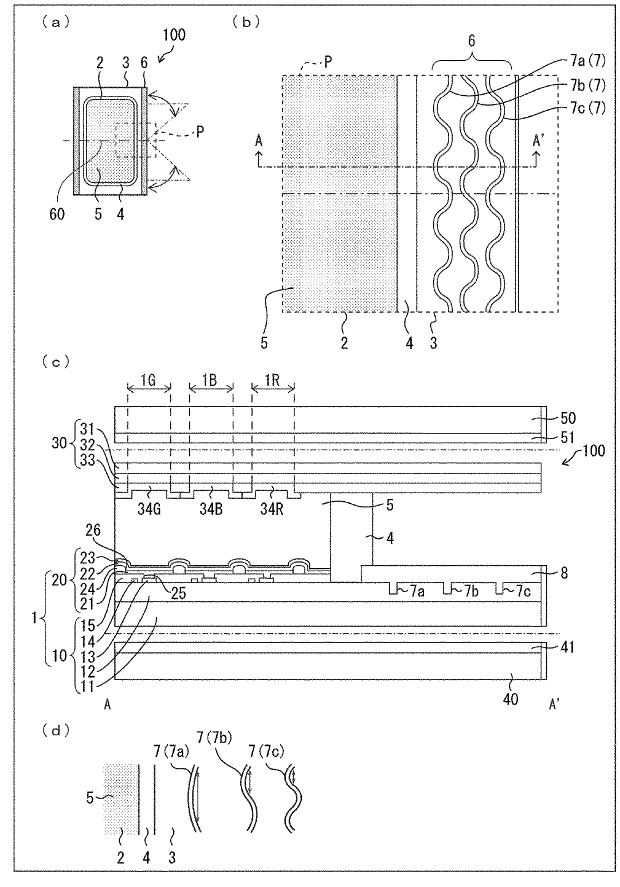
[0034](a) of FIG. 1 is a plan view schematically illustrating a configuration of an organic EL display panel in accordance with Embodiment 1. (b) of FIG. 1 is an enlarged view illustrating a broken-line box P of (a) of FIG. 1. (c) of FIG. 1 is an exploded cross-sectional view illustrating a configuration of a main part of the organic EL display panel in accordance with Embodiment 1 from which organic EL display panel carrier substrates have not been peeled off. (d) of FIG. 1 is a plan view illustrating other examples of a wavy recessed pattern.

[0035]Note that (c) of FIG. 1 corresponds to an exploded cross-sectional view taken along a line A-A′ of an organi...

embodiment 2

[0155]Embodiment 2 of the present invention will be described below with reference to (a) through (c) of FIG. 4. Note that for convenience, members having functions identical to those of the respective members described in Embodiment 1 are given respective identical reference signs, and a description of those members is omitted.

[0156](a) of FIG. 4 is a plan view schematically illustrating a configuration of an organic EL display panel in accordance with Embodiment 2. (b) of FIG. 4 is an enlarged view illustrating a broken-line box Q of (a) of FIG. 4. (c) of FIG. 4 is an exploded cross-sectional view illustrating a configuration of a main part of the organic EL display panel in accordance with Embodiment 2 from which organic EL display panel carrier substrates have not been peeled off.

[0157]Note that (c) of FIG. 4 corresponds to an exploded cross-sectional view taken along a line B-B′ of an organic EL display panel 200, which is illustrated in (b) of FIG. 4 and from which carrier sub...

embodiment 3

[0172]Embodiment 3 of the present invention will be discussed below with reference to (a) through (c) of FIG. 5. Note that for convenience, members having functions identical to those of the respective members described in Embodiments 1 and 2 are given respective identical reference signs, and a description of those members is omitted.

[0173](a) of FIG. 5 is a plan view schematically illustrating a configuration of an organic EL display panel in accordance with Embodiment 3. (b) of FIG. 5 is an enlarged view illustrating a broken-line box R of (a) of FIG. 5. (c) of FIG. 5 is an exploded cross-sectional view illustrating a configuration of a main part of the organic EL display panel in accordance with Embodiment 3 from which organic EL display panel carrier substrates have not been peeled off.

[0174]Note that (c) of FIG. 5 corresponds to an exploded cross-sectional view taken along a line C-C′ of an organic EL display panel 300, which is illustrated in (b) of FIG. 5 and from which carr...


PUM


Abstract

The present invention prevents an advance of a crack in a covering layer, without exposing a support. In a region between an edge part of a moistureproof layer (12) and a display region (2), wavy recessed patterns (7a, 7b, and 7c) are continuously or discontinuously provided so to connect one end of the moistureproof layer (12) and another end of the moistureproof layer (12). Each of the wavy recessed patterns (7a, 7b, and 7c) is recessed and is configured to change a direction in which a crack having appeared in the edge part of the moistureproof layer (12) advances.

Description

TECHNICAL FIELD[0001]The present invention relates to a flexible electronic device and a method of producing the flexible electronic device.BACKGROUND ART[0002]A flexible electronic device includes a flexible circuit substrate in which a circuit mainly including various elements and wires is provided on a flexible support covered with a covering layer. The covering layer is constituted by an inorganic insulating layer, and is referred to as a moistureproof layer, a protecting layer, a base insulating layer, or the like.[0003]Use of a flexible electronic device as an integrated circuit (IC) tag, an IC card, electronic paper, a flexible display device, or the like is under consideration from the viewpoint that the flexible electronic device is thin, light, and flexible.[0004]In particular, a so-called flexible display whose display part is flexibly deformable is drawing attention as a thin, light, and bendable display.[0005]A flexible display includes an electro-optic element, other c...

Claims


Application Information

Patent Timeline
IPC IPC(8): G09F9/30H01L51/50H05B33/04H05B33/14
CPCG09F9/30H01L51/50H05B33/04H05B33/14H05B33/22Y02E10/549Y02P70/50H10K59/12H10K77/111H10K2102/311H10K50/00
Inventor OCHI, TAKASHIYASUDA, YUKIOKAZAKI, SHOJISUGIMOTO, HIROSHIMISONO, KENJIHASEGAWA, MASAHIROWATANABE, NORIKOTSUDA, KAZUHIKO
Owner SHARP KK
Why Eureka
Try Eureka