Transition piece of combustor, and gas turbine having the same

a technology of combustor and gas turbine, which is applied in the direction of machines/engines, combustion types, lighting and heating apparatus, etc., can solve the problems of prone to concentration of stress and tend to crack

Active Publication Date: 2014-05-29
MITSUBISHI POWER LTD
View PDF1 Cites 15 Cited by
  • Summary
  • Abstract
  • Description
  • Claims
  • Application Information

AI Technical Summary

Benefits of technology

[0011]That is, according to the transition piece of the invention, even if a distance between adjacent cooling air passages is reduced more than that in the past to improve the cooling effect of the body wall, it is possible to suppress the growth of the cracks.
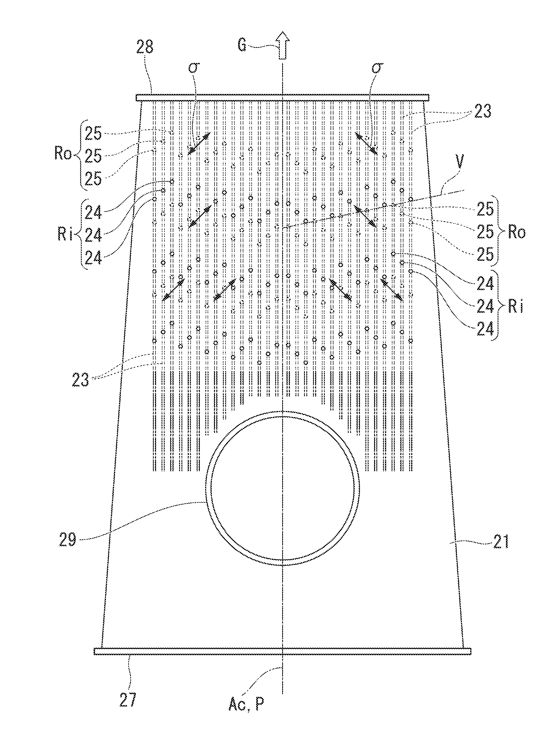
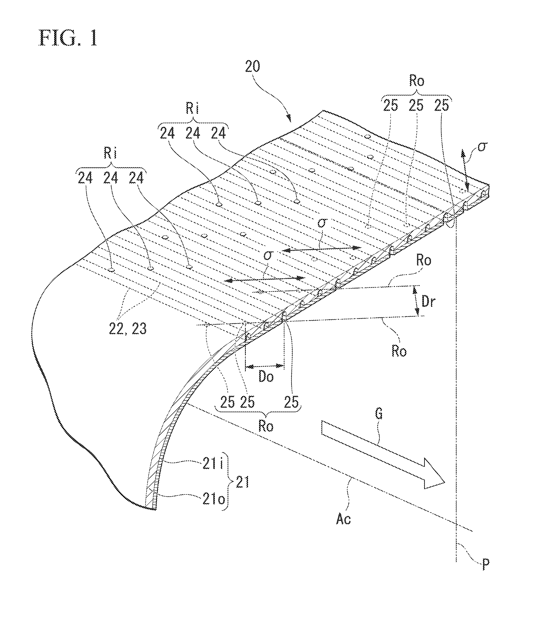
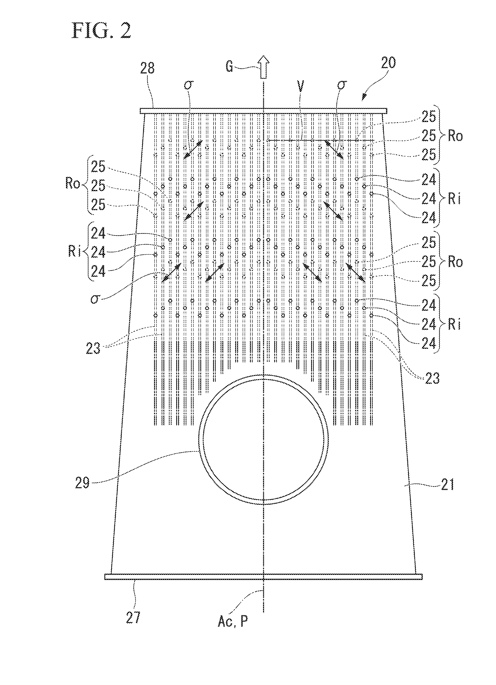
[0013]When high temperature combustion gas flows in the body wall formed in a cylindrical shape, a principal stress is applied to one side part of the body wall with respect to the hypothetical planein a direction that is closer to the hypothetical plane toward the rear end of the transition piece and a principal stress is also applied to the other side part of the body wall with respect to the hypothetical planein a direction that is closer to the hypothetical plane toward the rear end of the transition piece. For this reason, the plurality of cooling air outlet ports, which are formed at the one side part with respect to the hypothetical plane, are arranged in the direction where the principal stress is applied to form lines; and the plurality of cooling air outlet ports, which are formed at the other side part with respect to the hypothetical plane, are also arranged in the direction where the principal stress is applied to form lines. Accordingly, it is possible to suppress the growth of the cracks at both side parts of the hypothetical plane in the transition piece.
[0017]In general, the cross-sectional area of the transition piece is gradually reduced toward the rear end. For this reason, the flow rate of combustion gas flowing in the transition piece is gradually increased toward the rear end of the transition piece. Accordingly, the heat input from the combustion gas at the downstream portion of the transition piece is larger than that at the upstream portion of the transition piece. It is possible to improve the cooling effect of the downstream portion of the body wall by making the distance between the cooling air passages short while suppressing the growth of the cracks at the downstream portion, where the heat input from combustion gas is relatively large, in the transition piece.
[0022]In the gas turbine, it is possible to suppress the growth of cracks in the body wall even if a distance between a plurality of cooling air passages is reduced than that in the past to obtain a high cooling effect in a body wall forming a transition piece.

Problems solved by technology

Cracks tend to occur in the body wall of the transition piece from the cooling air outlet ports first, where the thermal environment is severe and stress is apt to be concentrated.

Method used


Image

  • Transition piece of combustor, and gas turbine having the same
  • Transition piece of combustor, and gas turbine having the same
  • Transition piece of combustor, and gas turbine having the same

Examples


Embodiment Construction

[0032]A gas turbine according to an embodiment of the invention will be described in detail below with reference to FIGS. 1 to 7.

[0033]As shown in FIG. 7, a gas turbine according to this embodiment includes a compressor 1 that generates compression air by compressing outside air; a plurality of combustors 10 that generates combustion gas by mixing fuel, which is supplied from a fuel supply source, with compression air and combusting a mixture of the fuel and the compression air; and a turbine 2 that is driven by the combustion gas.

[0034]The turbine 2 includes a casing 3 and a turbine rotor 4 that is rotated in the casing 3. The turbine rotor 4 is connected, for example, to a generator (not shown) that generates electricity by the rotation of the turbine rotor 4. The plurality of combustors 10 is fixed to the casing 3 so as to be disposed around a rotation axis Ar of the turbine rotor 4 at regular intervals in the circumferential direction.

[0035]As shown in FIG. 6, the combustor 10 i...


PUM


Abstract

A transition piece of a combustor that sends high temperature combustion gas to a turbine includes a cylindrical body wall and cooling air passages. The passages are formed in the body wall so as to extend in an axial direction thereof, and each of the passages has cooling air inlet ports opened at an outer circumferential surface of the transition piece and cooling air outlet ports opened at an inner circumferential surface of the transition piece. The cooling air outlet ports form a plurality of lines in a direction oblique with respect to the axial direction of the body wall. A first distance between a first line of the cooling air outlet ports and a second line of the cooling air outlet ports adjacent to the first line is larger than a second distance between the cooling air outlet ports adjacent to each other.

Description

TECHNICAL FIELD[0001]The present invention relates to a transition piece of a combustor and a gas turbine having the same.BACKGROUND ART[0002]A combustor of a gas turbine includes a transition piece that sends high-temperature and high-pressure combustion gas to a turbine.[0003]A body wall forming the transition piece has a structure that guides cooling air into the body wall in order to prevent the burnout of the transition piece. Specifically, a plurality of cooling air passages, which extend in the axial direction of the transition piece, are formed in the body wall, and a cooling air inlet port opened to the outer circumferential surface of the body wall and a cooling air outlet port opened to the inner circumferential surface of the body wall are formed at each of the plurality of cooling air passages. Cooling air is introduced into the cooling air passages from the cooling air inlet ports, and flows into the transition piece from the cooling air outlet ports.[0004]The cooling ...

Claims


Application Information

Patent Timeline
Patent Type & Authority Applications(United States)
IPC IPC(8): F01D9/02
CPCF05D2260/202F05D2250/314F01D9/023F23R3/06F02C7/18F23D2203/1055
Inventor KISHIDA, HIROAKI
Owner MITSUBISHI POWER LTD
Why Eureka
Try Eureka