Translating carriage exercise machines and methods of use

a carriage and exercise machine technology, applied in the field of exercise machines, can solve the problems of lack of features found in the higher end machines, inconvenient use, and inconvenient use, so as to reduce the multi-axial stability of the reformer, prevent sagging, and adjust the stiffness

Active Publication Date: 2018-06-21
JANOWSKI BRIAN PATRICK
View PDF0 Cites 28 Cited by
  • Summary
  • Abstract
  • Description
  • Claims
  • Application Information

AI Technical Summary

Benefits of technology

[0208]In one form, a proximal end of a carriage rope may be biased to curl around the remaining rope in the overlap portion to prevent sagging. For example, an curled nitinol wire may be placed internal to the rope.
[0209]The legs on typical Reformers are made of a rigid material and may be used effectively on the disclosed embodiment.
[0210]In one form, a Reformer is configured with one or more of resilient feet and legs. The feet and legs may be in the form of one or more of; coil springs, leaf springs, wafer springs, gas or liquid filled bags or cylinders, and various resilient pillows of varying durometers of polyurethane or the like. The resilient legs reduce the multi-axial stability of a Reformer during exercise thereby providing the user a balance training benefit to their neurological system.
[0211]In one form, resilient legs are adjustable in stiffness. For example, various levels of gas may be added to a filled bag to make it stiffer. In another example, a stiffer grade of polyurethane may be chosen.
[0212]In one form, resilient legs may include a lock out feature that quickly turns the legs from a resilient form to a stable rigid configuration or within a range therebetween.
[0213]In some forms, resilient feet include an upper foot mount portion for attaching to a frame portion of a translating carriage exercise machine and a lower foot pad portion for resting to the floor. Included at the bottom of the lower foot pad portion may be a frictional floor element such as a soft rubber shell to minimize sliding of the foot on the floor.

Problems solved by technology

To many users, less expensive Reformers feel poorly constructed, are incorrectly sized, and lack many features found in the higher end machines although many users view the higher end machines as too expensive.
With the carriage in a resting position biased toward the foot end of the machine, the distance between the footbar and the carriage shoulder rests cannot be adjusted for the height of the user.
The mechanics required to make these footbars adjustable along a plane and about an axis is expensive to manufacture and can be confusing for the user to operate.
In addition, when the footbar is translated toward the carriage to accommodate height of shorter users, the footbar is translated toward the head end of the machine causing the user to experience a loss in potential carriage travel during exercise.
Although many users find the Reformer to be useful for toning, stretching, and strengthening, the Reformer is not known as a great aerobic machine.
This requires additional machine space that most users do not have in their homes, clinics, studio, or exercise facility.
The current boards in the art are often too rigid.
Other jump boards using a trampoline style surface are too soft.
Another costly part of some Reformers is the rope adjustment mechanism attached to the carriage.
The mechanisms required to perform this task add significant cost to the machine.

Method used


Image

  • Translating carriage exercise machines and methods of use
  • Translating carriage exercise machines and methods of use
  • Translating carriage exercise machines and methods of use

Examples


Embodiment Construction

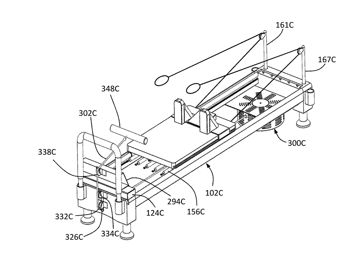
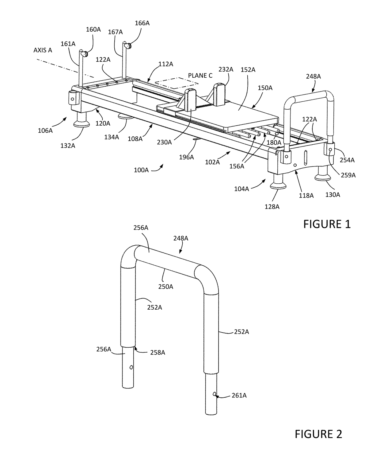
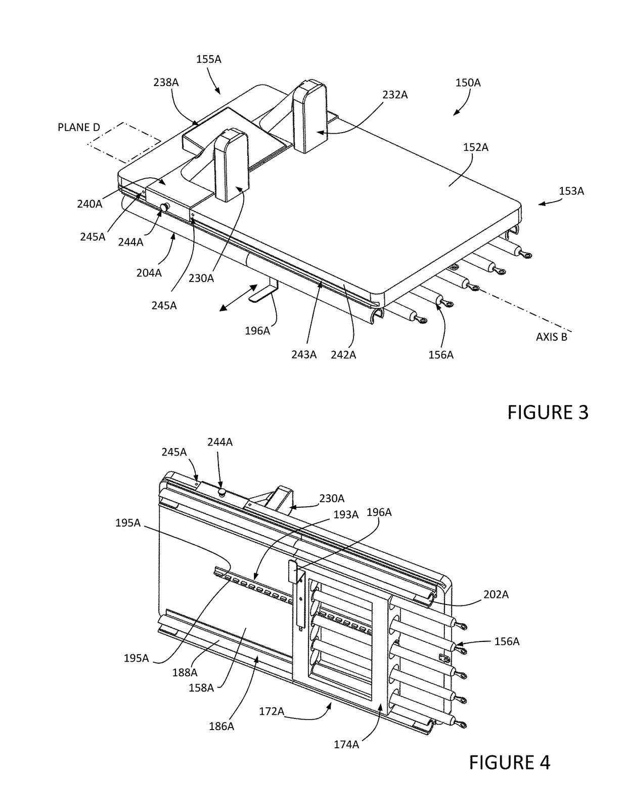
[0318]Select embodiments of the invention will now be described with reference to the Figures. Like numerals indicate like or corresponding elements throughout the several views and wherein various embodiments are separated by letters (i.e. 100B, 100C, 100D). The terminology used in the description presented herein is not intended to be interpreted in any limited or restrictive way, simply because it is being utilized in conjunction with detailed description of certain specific embodiments of the invention. Furthermore, embodiments of the invention may include several novel features, no single one of which is solely responsible for its desirable attributes or which is essential to practicing the invention described herein. A multitude of improvements to translating carriage exercise machines such as Reformers are introduced in this document. It is recognized that any one or more improvements introduced in this document may be individually or collectively used to upgrade existing or ...


PUM


Abstract

A translatable carriage exercise machine comprising first and second spaced elongate side rails. A moveable carriage translatable along the side rails. An upper support surface on the carriage sized to support the entire posterior trunk of an adult human in supine. A plurality of elastic tension members secured to a bottom of the moveable carriage and fixable to a plurality of spring anchors. An upright footbar positioned at a machine first end. A pair of carriage pulleys fixed at a second end of the exercise apparatus with carriage ropes adjustably fixed to the moveable carriage each looped around respective carriage pulleys. A rotational resistance mechanism comprising an elongate resistance band having an extended configuration and a retracted configuration. The rotational resistance mechanism comprising a resistor comprising a load member. A user option to utilize one or more of the elastic tension members and rotational resistance mechanism during exercise.

Description

CROSS REFERENCE TO RELATED APPLICATIONS[0001]This application claims priority to Provisional Patent Application No. 62 / 437,546 filed Dec. 21, 2016, and Provisional Patent Application No. 62 / 545,453 filed Aug. 14, 2017 the entire disclosures of which are hereby incorporated by reference and relied upon.BACKGROUND OF THE INVENTIONField of the Invention[0002]The invention relates generally to exercise machines, and more particularly to exercise machines comprising a translating carriage for supporting all or a portion of a user's body weight.Description of Related Art[0003]Decades after Joseph Pilates invented his Reformer, manufacturers and health and fitness professionals from around the world continue to improve the machine and the method of use. Competitors in this market space include Balanced Body®, Stott®, Peak®, Stamina Fitness®, and Total Gym® to name a few.[0004]One of the most common forms of translating carriage exercise machine is referred to as a Reformer. The typical Ref...

Claims


Application Information

Patent Timeline
Patent Type & Authority Applications(United States)
IPC IPC(8): A63B22/00A63B21/055A63B21/00A63B21/22A63B21/04A63B69/00A63B23/035
CPCA63B22/0076A63B22/0089A63B21/0552A63B21/154A63B21/22A63B21/153A63B21/0442A63B21/4035A63B21/4045A63B69/0057A63B23/03566A63B2225/09A63B2210/50A63B2022/0079A63B21/0557A63B2225/102A63B2209/00A63B21/055A63B21/068A63B22/203A63B21/00065A63B21/023A63B21/0428A63B21/4033A63B21/4043A63B23/1209A63B22/0087A63B69/06
Inventor JANOWSKI, BRIAN PATRICK
Owner JANOWSKI BRIAN PATRICK
Why Eureka
Try Eureka