Fitting for laying decking boards

a technology for connecting panels and decking, applied in the direction of flooring, covering/lining, construction, etc., can solve problems such as deformation of floor surfaces, and achieve the effect of convenient movemen

Active Publication Date: 2018-06-21
ALFER ALUMINUM
View PDF44 Cites 0 Cited by
  • Summary
  • Abstract
  • Description
  • Claims
  • Application Information

AI Technical Summary

Benefits of technology

[0008]The fitting according to the invention has at least two fastening devices which serve for the one part for fastening to a board and for the other part for fastening the fitting to a substructure. These two fastening devices may be of identical or different types, and may also be fastening means themselves, but fastening devices of a passive type, in particular through-openings, are preferred. The first fastening device is arranged on the fitting such that, in use, it is arranged in the region covered by a board, and the second is arranged such that it is not covered. The main body can in this case have any desired circumferential shape, as long as it has a portion which is arranged under a board in use and has two portions which are not arranged under the board. In particular, the main body can be triangular, rectangular, square, oval, round, polygonal or the like, rectangular shapes being preferred. The spacer is arranged predominantly at right angles to the main body in the operating state of the fitting, with the result that it allows the board to rest optimally on its surface. The expression “predominantly at right angles” is understood here to include angles in the range from 90°±2.5°. The invention thus proposes, with a great advantage, designing the main body and spacer to be connectable together in a releasable manner by means of a third connecting device. This has the great advantage that the spacer is removable from the joint after the board has been laid, such that it does not hinder the dimensional change thereof and at the same time realizes a cleanly worked joint. At the same time, this has the advantage that fundamentally differently shaped, in particular thick, spacers can be provided and can be connectable to a main body, such that one type of main body is sufficient to realize different joint widths.
[0009]The development of the invention according to which the third fastening device is in the form of a plug-in slot is particularly advantageous. A plug-in slot, that is to say a male / female configuration of the third connecting device, simplifies and accelerates the connecting of the two components of the fitting, wherein especially the removal of the spacer from a joint is easy, it being sufficient just to pull on the spacer. More complicated manners of fastening are advantageously avoided. According to the invention, each of the two components can in this case be configured in either a male or a female manner, wherein the other is then formed in each case in the opposite manner. In particular, the fitting can have a peg over which a bore of the spacer engages, or the fitting can have a receiving opening, such as a blind hole, in which a correspondingly shaped part of the spacer engages. The latter is preferred, since in this way the main body can be configured as an extruded or injection-moulded part which has only smooth surfaces without projecting parts, thereby additionally also reducing the risk of injury to a user.
[0012]Furthermore, the invention proposes that the through-opening have an H-shaped cross-sectional area, wherein a connecting portion of the H shape extends parallel to the shorter side and orthogonally to the longer side of the main body. Generally, the through-opening can be formed with any cross-sectional shape, in particular a rectangular or a square or a round one. It can thus be selected irrespective of the cross-sectional shape of the spacer which is provided in the axial region thereof that serves for bearing on a board. A rectangular shape, or an H shape, is particularly preferred, however, since this allows a secure hold and the spacer can be formed with a cross-sectional area that is uniform and constant along its axial course, resulting in a spacer that is held in a structurally particularly simple manner. The spacer can thus be anchored particularly well with the two ends of the through-opening, which are thickened compared with the connecting portion.
[0013]In one configuration of the invention, the connecting portion has at least one, preferably several, in particular three protrusions projecting into it. The protrusions can in turn have any desired cross-sectional area in this case, as long as they constrict the free diameter of the connecting portion, with the result that they represent an obstacle for the plugging of the spacer into the through-opening in the third fastening device that is easy to overcome by light force exertion. As a result, additional stability of the spacer in the plug-in slot of the main body of the fitting is ensured by a force fit and slipping of the spacer through the through-opening is limited even in the event of a lack of constriction of the opening or a lack of widening of the spacer. From a production point of view, simple punching of the through-opening and of the spacer is thus allowed. A relatively large number is in this case considered to be advantageous for the number of protrusions in the connecting region of the H-shaped through-opening, since a relatively small number of protrusions can result in twisting or tilting of the spacer in the through-opening. An excessively large number of protrusions, by contrast, requires a relatively large force to be exerted for the plugging in and the releasing of the spacer from the plug-in slot. Although this results in particularly high stability of the connection of the main body and spacer, it counteracts the basic idea of the plug-in system being easy to release. Therefore, three protrusions in particular are considered to be advantageous according to the invention.
[0016]Furthermore, the invention advantageously proposes that the main body have at least one groove extending orthogonally to the longer side. Ideally, the main body, which is wider than the board width, has two grooves, wherein the grooves are arranged on the fitting such that they are a board's width away from one another. The technical benefit of the grooves resides in marking that region which is located under the board in use. This ensures that the second and third connecting devices are freely accessible and not blocked. This also ensures that the spacer bears against the board, in particular flat against the board. If a board has to be attached in the vicinity of an obstacle such as a pillar or a wall, it is possible for those parts of the fitting that project under the board and serve to fasten it to the supporting surface to prevent clean insertion of the board at said point. The grooves allow clean removal of the disruptive part here, too, with the orientation being maintained by way of the grooves.
[0026]The invention proposes that the spacers of a fitting that has just been laid be removed and / or that steps a) and b) be interchanged. This has the advantage that it is easily possible to move on the partially laid board floor without spacers protruding depending on length.

Problems solved by technology

A drawback of this prior art is that these spacers bear firmly against adjacent boards and thus at least locally prevent the dimensions of the completely fitted boards from changing, this then possibly resulting in deformation of the supporting structure and / or deformation of the floor surface, this resulting in fundamentally dangerous tripping hazards.
A further drawback is that these spacers define a particular joint width, although it may be appropriate, depending on the board material to be laid, to configure the joint widths to be selectable.

Method used


Image

  • Fitting for laying decking boards
  • Fitting for laying decking boards
  • Fitting for laying decking boards

Examples


Embodiment Construction

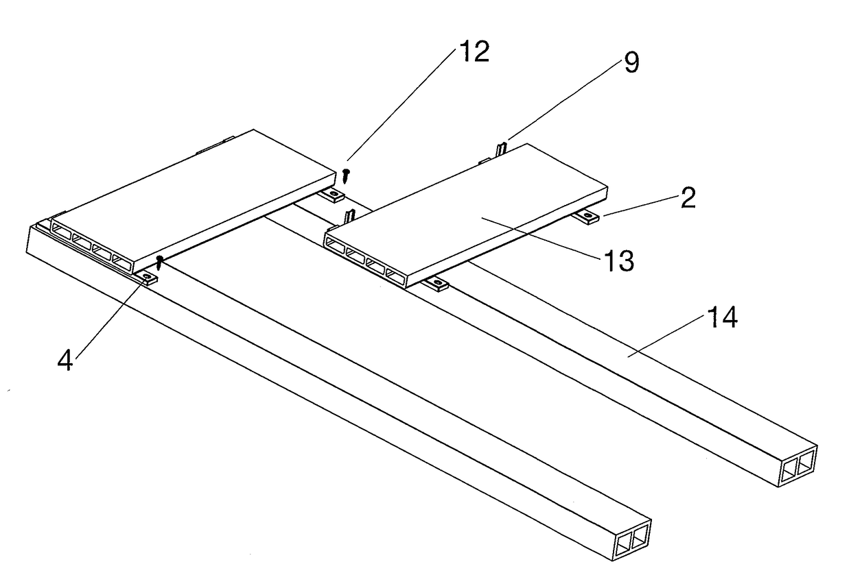
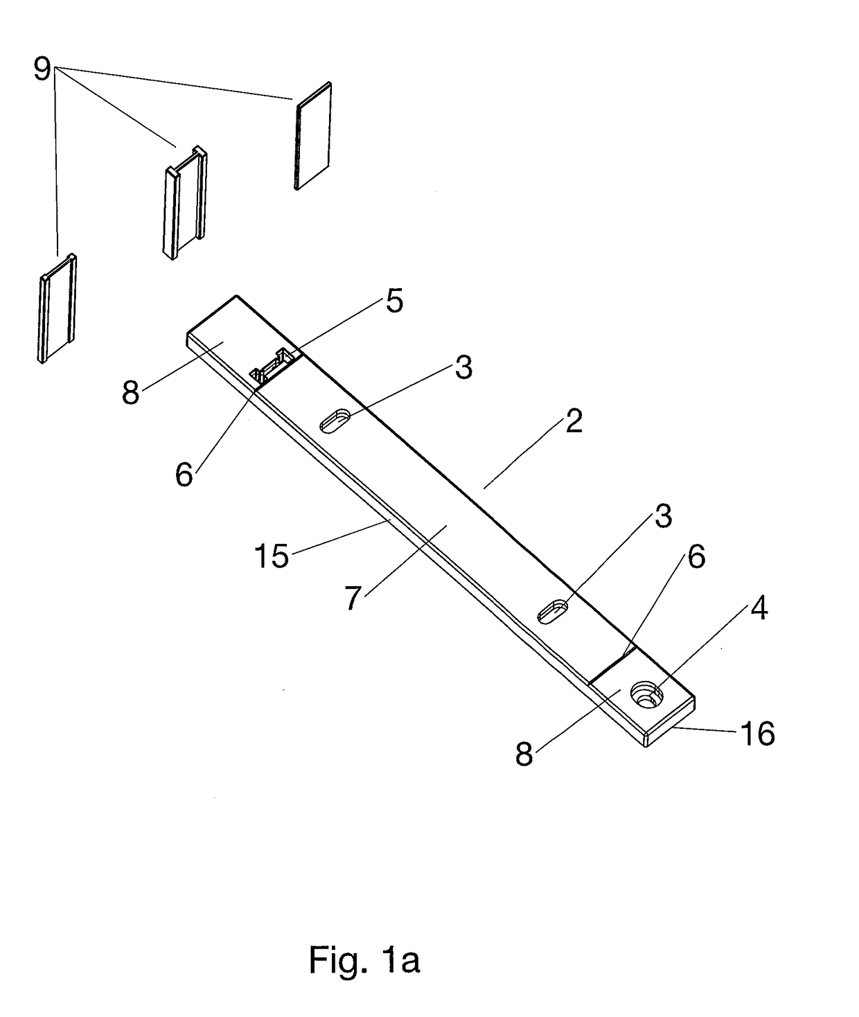
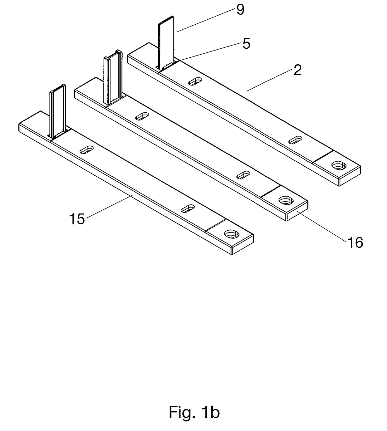
[0035]FIGS. 1a and 1b show an elongate, rectangular main body 2 according to the invention, having two longer sides 15 and two shorter sides 16, said main body 2 having three different fastening devices 3, 4, 5. The first fastening device 3 is provided twice as a through-opening in the form of an oblong hole in the central region 7 of the main body 2, in particular with the long side parallel to the shorter sides 16. These advantageously allow the fitting to shift when the dimensions of the board change, without a screw that passes through the oblong hole tearing out. Of course, round or polygonally configured through-openings are also in accordance with the invention, in particular when carriage bolts are intended to be used as fastening means. The second fastening device 4 is likewise in the form of a through-opening, but in this case with a stepped radius, as seen axially, in order to allow a fastening means 12 to be countersunk, resulting in a flat surface. This allows clean int...


PUM


Abstract

The invention relates to a fitting for connecting and laying panels, boards or planks on a supporting body, having a main body and a spacer, wherein the main body has at least two fastening devices for connecting the fitting and board and for connecting the fitting and supporting surface, wherein the spacer and main body are arranged predominantly at right angles to one another in the operating state, characterized in that the main body and spacer are connectable together in a releasable manner by a third fastening device.

Description

FIELD AND BACKGROUND OF THE INVENTION[0001]The invention relates to a fitting for connecting panels, boards or planks, collectively referred to as boards in the following text, having a supporting body, in particular in the field of decking or other outdoor areas.[0002]Boards are generally screwed to a supporting structure in a manner arranged parallel to one another via a fitting attached to the board. This supporting structure can comprise spaced-apart beams or be a uniform surface, for example a surface consisting of OSB panels, concrete or other materials, to which the boards are attached. In this case, the boards subsequently to be laid are oriented with respect to the already laid boards in terms of parallelism and spacing, wherein joints form between the boards. Depending on the material and prevailing environmental conditions, the dimensions of the boards change, i.e. the size of the joint changes over time. In order to obtain a uniform joint pattern, it is known to provide ...

Claims


Application Information

Patent Timeline
Patent Type & Authority Applications(United States)
IPC IPC(8): E04F15/02
CPCE04F2015/02072E04F2201/0511E04F15/02044E04F15/02183E04F21/0092E04F2203/04E04F15/02E04F21/00
Inventor WILBS, THOMAS
Owner ALFER ALUMINUM
Why Eureka
Try Eureka