Realtime payload mapping for loader/hauler system optimization

a real-time payload mapping and loader/hauler technology, applied in soil shifting machines/dredgers, construction, etc., can solve the problems of operator difficulty in properly balancing each load, operator may not be able to properly view the previously placed loads, operator may be unable to pick out the best place,

Inactive Publication Date: 2018-06-28
CATERPILLAR INC
View PDF4 Cites 27 Cited by
  • Summary
  • Abstract
  • Description
  • Claims
  • Application Information

AI Technical Summary

Problems solved by technology

As a result, it may be difficult for the operator to properly balance each load when placing it into the hauling machine.
For example, the operator may not be able to properly view the previously placed loads.
Therefore the operator may be unable to pick out the best place to dump subsequent loads of work material into the hauling body.
Additionally, some operators may not have sufficient knowledge or training in the proper loading techniques for the variety of work machines present at the jobsite.
However, the '869 publication does not visually scan the dump truck bed to produce an image map of the dump truck bed which is analyzed to determine an optimized location for the excavator to place the load on the dump truck.

Method used


Image

  • Realtime payload mapping for loader/hauler system optimization
  • Realtime payload mapping for loader/hauler system optimization
  • Realtime payload mapping for loader/hauler system optimization

Examples


Embodiment Construction

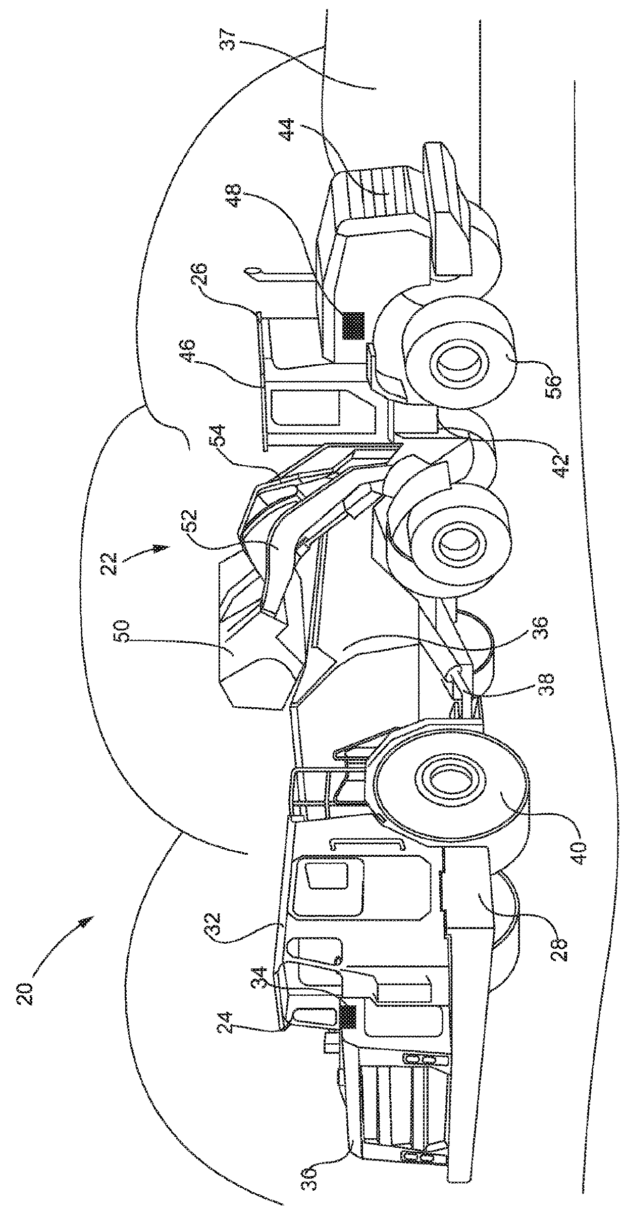
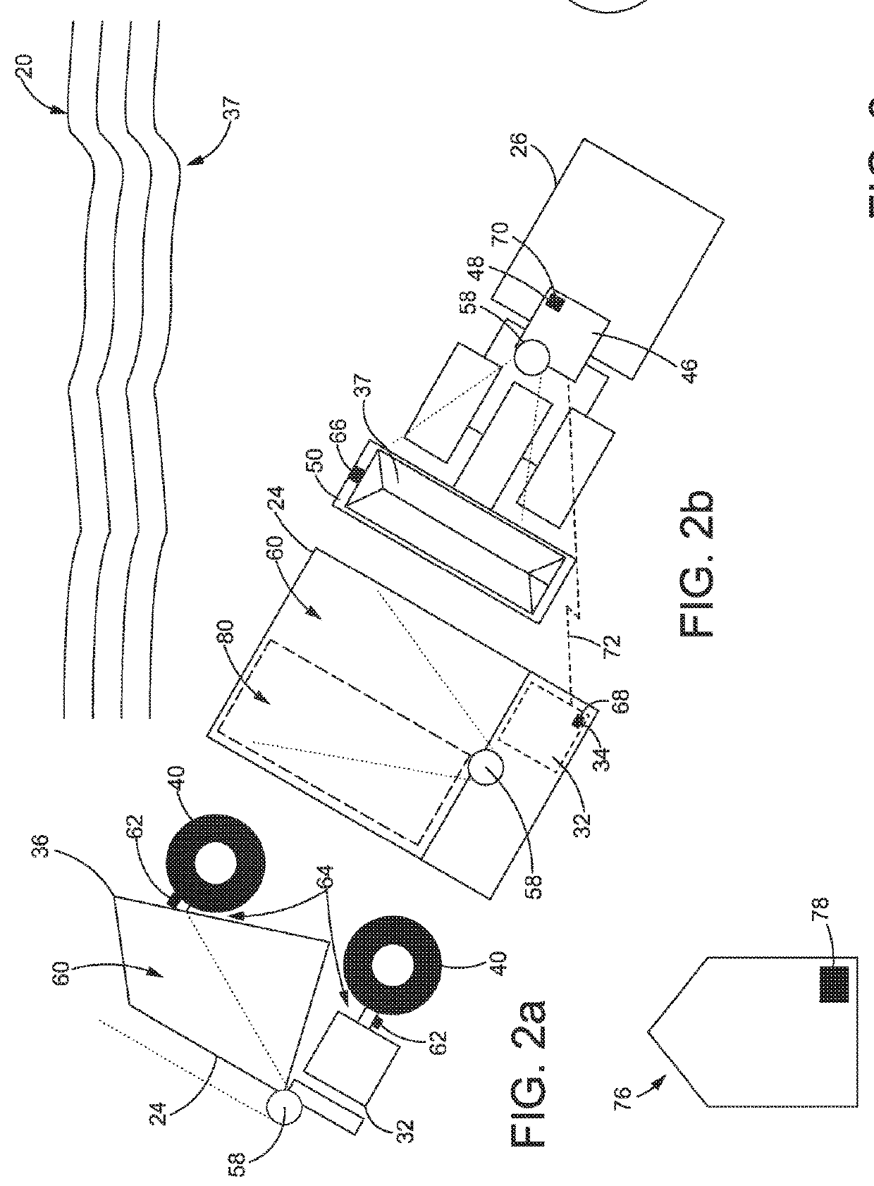
[0019]Referring now to the drawings and with specific reference to FIG. 1, a jobsite 20 with a set of work machines 22 is shown, in accordance with certain embodiments of the present disclosure. While one non-limiting example of the set of work machines 22 may include a hauling machine 24 and a loading machine 26, it will be understood that the set of work machines 22 may include other types of machines such as but not limited to, an on-road truck, an off-road truck, a motor grader, industrial mining equipment, a locomotive, and any other such machines. The hauling machine 24 may include a frame 28 configured to support a power source 30, and an operator compartment or operator cabin 32. In some embodiments, the power source 30 may be a power generating source such as but not limited to, a diesel combustion engine, a gasoline combustion engine, a generator, an electric motor, any other known power generating source or a combination thereof. Moreover, the operator compartment 32 may ...


PUM


Abstract

A payload optimization system is disclosed and may include one or more visual sensors operably coupled to a hauling machine and configured to scan and produce a payload body data set. The system may further include a loading machine including a payload bucket configured to load a payload into the payload body. Moreover, a loading system controller may be communicably coupled to each of the hauling machine and the loading machine and configured to identify the hauling machine and the loading machine using a set of machine identifiers. Moreover, the controller may receive the payload body data set from the one or more visual sensors, generate a payload body map, and program a loading sequence of the payload body based on the payload body map. The loading system controller may transmit and display the loading sequence configured to guide a loading cycle between the hauling machine and the loading machine.

Description

FIELD OF THE DISCLOSURE[0001]The present disclosure relates generally to hauling and loading machines and, more particularly, relates to a system for optimizing the loading of a hauling machine.BACKGROUND OF THE DISCLOSURE[0002]Work machines, such as hauling trucks, loaders, shovels, excavators, articulated trucks, off-road machines, on-road machines, dozers, and the like may be used in mining, construction, agriculture, petroleum, and other such applications. During operation, one or more work machines may work together to perform a desired task. In one non-limiting example, a hauling machine and a loading machine may be paired together at a jobsite. The loading machine may be tasked with scooping up material in a loading bucket and filling a hauling body of the hauling machine. In some cases the loading machine may be configured to scoop and load a variety of work material into the hauling machine such as large rocks or boulder, small rocks, gravel, dirt, and the like.[0003]Typica...

Claims


Application Information

Patent Timeline
Patent Type & Authority Applications(United States)
IPC IPC(8): E02F9/20
CPCE02F9/2025E02F9/205E02F9/262
Inventor BARTSCH, CHRISROBINSON, MARK A.TAYLOR, JEFFREY C.
Owner CATERPILLAR INC
Why Eureka
Try Eureka