Lawn mower
a lawnmower and mower technology, applied in the field of lawnmowers, can solve the problem of low operation of the discharge outlet door
- Summary
- Abstract
- Description
- Claims
- Application Information
AI Technical Summary
Benefits of technology
Problems solved by technology
Method used
Image
Examples
first embodiment
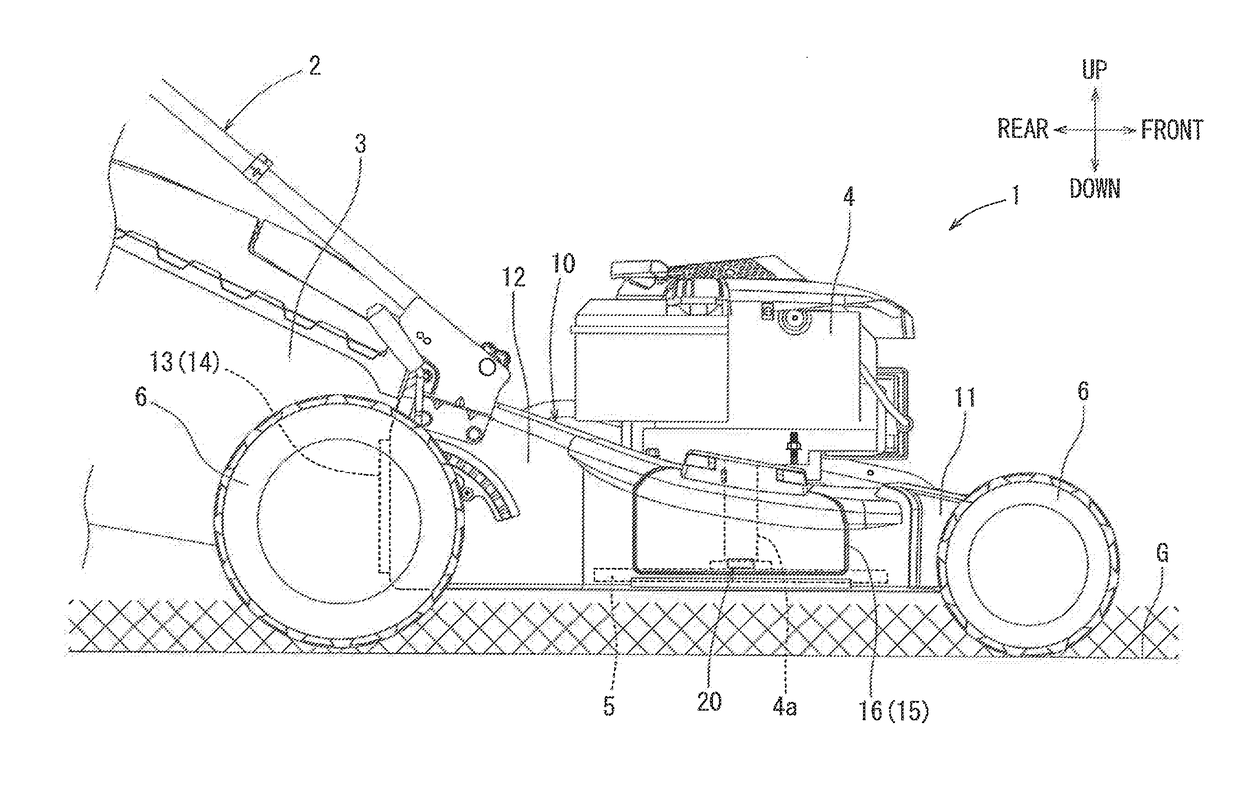
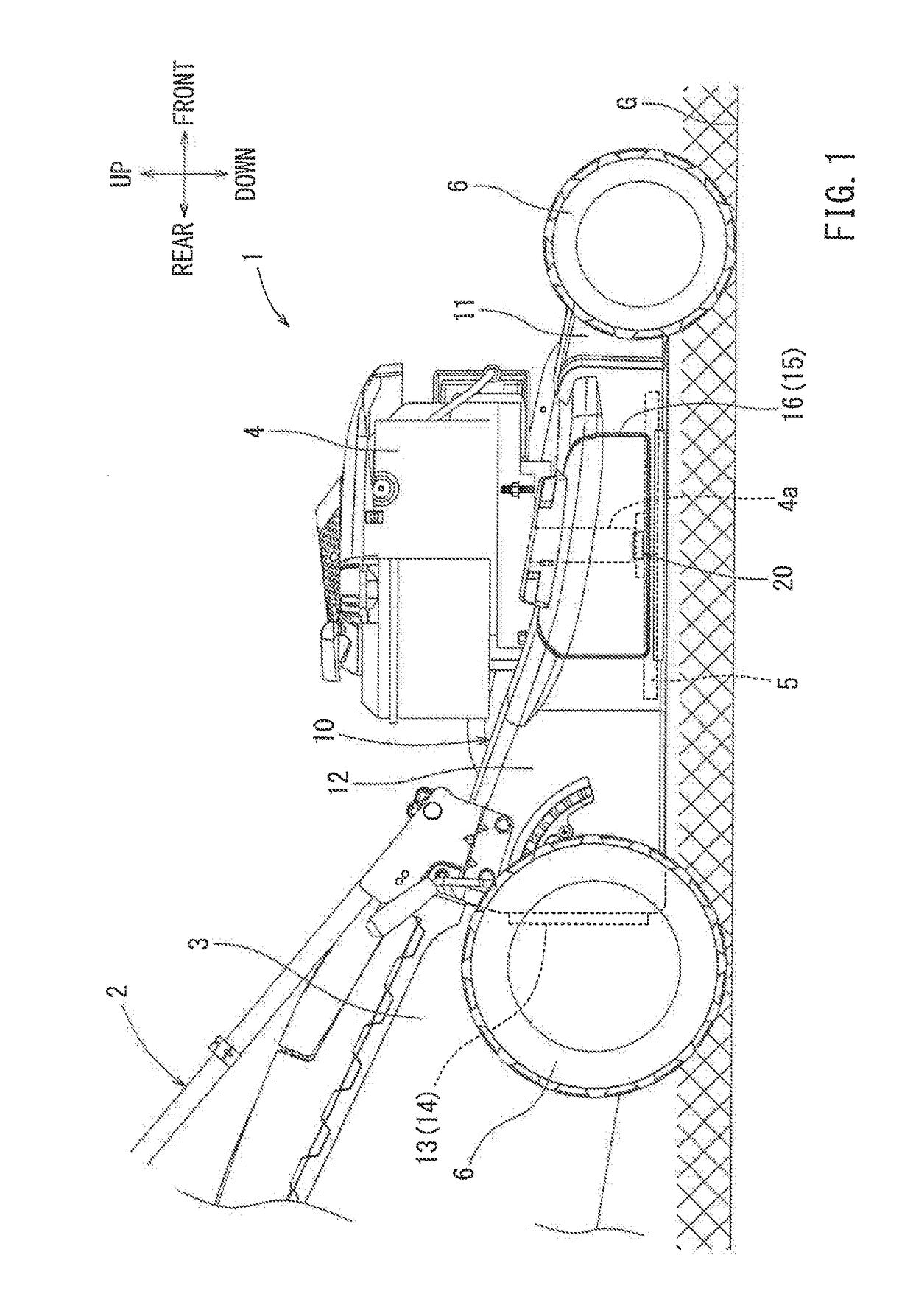
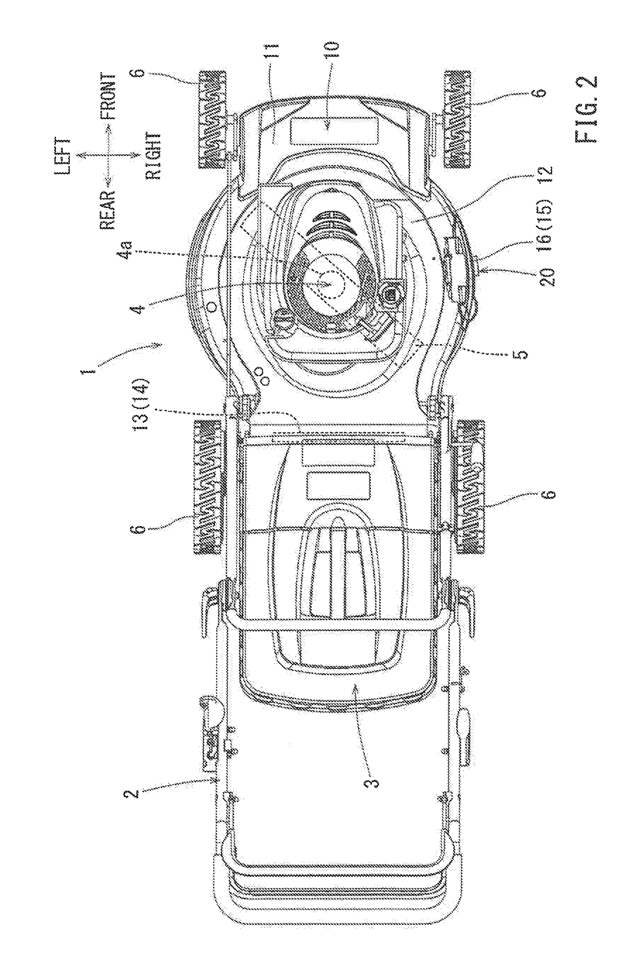
[0038]According to the lock device 20 of the first embodiment configured as described above, the discharge outlet door 16 is reliably locked at the closed position. Therefore, in comparison with the construction in which the closed position is held only by the biasing force of the torsion spring, it is possible to reliably prevent fluttering of the discharge outlet door 16. Because the fluttering is prevented by the lock device 20, it is possible to set the biasing force of the torsion spring 18 to be weaker. Therefore, it is possible to easily open the discharge outlet door 16 by a smaller force than in the prior art, and as a result, it is possible to improve the usability of the lawn mower 1 in this respect.
[0039]Further, the discharge outlet door 16 is locked at the closed position by the lock device 20. The unlock operation of the lock device 20 is caused by the unlock operation of the lock member 21 by the user. Therefore, it is possible to reliably prevent the discharge outle...
third embodiment
[0049]In this way, also according to the lock device 40 of the third embodiment, in order to open the discharge outlet door 16 locked at the closed position, it is necessary for the user to press the knob portion 41a downward for the unlocking operation of the lock device 40. For this reason, it is possible to prevent the discharge outlet door 16 from being accidentally opened by the blowing pressure, vibrations, etc. generated by the rotation of the mowing blade 5. Further, by the lock device 40, the closed state of the discharge outlet door 16 is automatically locked, and therefore, it is possible to obviate troubles such as forgetting of the lock operation. Hence, also in this respect, it is possible to avoid accidental opening or fluttering of the discharge outlet door 16. Further, because the closed state of the discharge outlet door 16 is locked by the lock device 40, the torsion spring 18 can be set to be weak to enable the discharge outlet door 16 to be easily opened by a sm...
second embodiment
[0052]As the discharge outlet door 16 is closed from the open state, the engaging portion 54 moves over the lock receiving portion 55 against the biasing force of the torsion spring that is adapted to hold the lock position, due to an inclined surface action similar to that of the guide including surfaces 21a and 22a of the second embodiment, so that the discharge outlet door 16 can be automatically locked at the closed position.
[0053]FIG. 8 shows a lock device 60 according to a fifth embodiment. Similar to the fourth embodiment, the lock device 60 of the fifth embodiment may be disposed near the corner portion on the rear side of the lower portion of the discharge outlet door 16. A handle 61 of the fifth embodiment may be arranged so as to be liftable in the up and down directions via a support shaft 62. The handle 61 is biased toward a lock position by a torsion spring, the illustration of which is omitted. FIG. 8 shows a state where the handle 61 has returned to the lock position...
PUM
 Abstract
Description
Claims
Application Information
 - R&D
- Intellectual Property
- Life Sciences
- Materials
- Tech Scout
- Unparalleled Data Quality
- Higher Quality Content
- 60% Fewer Hallucinations
Browse by: Latest US Patents, China's latest patents, Technical Efficacy Thesaurus, Application Domain, Technology Topic, Popular Technical Reports.
© 2025 PatSnap. All rights reserved.Legal|Privacy policy|Modern Slavery Act Transparency Statement|Sitemap|About US| Contact US: help@patsnap.com


