Automated ECG Analysis and Diagnosis System

a technology which is applied in the field of automatic ecg analysis and diagnosis system, can solve the problems of inability to observe the ecg waveform with the naked eye, the accuracy rate of diagnosis has always been a problem in clinical applications, and the complexity of ecg science is one of the most complicated disciplines in medicin

Active Publication Date: 2018-07-05
CHEN GUANGREN +2
View PDF1 Cites 10 Cited by
  • Summary
  • Abstract
  • Description
  • Claims
  • Application Information

AI Technical Summary

Problems solved by technology

Since the first ECG instrument was invented in 1903, its accuracy rate for diagnosis has always been a problem in clinical applications.
As a result, ECG science is one of the most complicated disciplines in medicine.
However, generally one is unable to observe this from a conventional linear ECG waveform with the naked eye.
However, wide clinical use of such systems has yet to be achieved.
As a result, all ECG parameters are, in general, not accurate, and it is almost impossible to measure these parameters after the waveform changes.
Also, this accuracy is only achieved for simple ECG waveform variations and not for many complex waveforms.
As a result, information specific to these different parts of the heart muscle are generally lost.
For example, in many cases, conventional ECG waveforms show abnormal results in tests of normal people and also show normal results in tests of abnormal people, which makes it extremely difficult for clinical reading and understanding and makes it impossible to determine whether a result is normal or abnormal.
ECG remains one of the most extensively used clinical tools used at present along with blood tests and imaging, despite the lack of accurate systems for automated ECG analysis and diagnosis.
This is the conventional ECG waveform measurement problem.
Unfortunately, however, the P, Q, R, S, T, U, and J waveforms do not provide a complete picture of the operation of all the different muscle tissues of the heart.

Method used


Image

  • Automated ECG Analysis and Diagnosis System
  • Automated ECG Analysis and Diagnosis System
  • Automated ECG Analysis and Diagnosis System

Examples


Embodiment Construction

Computer-Implemented System

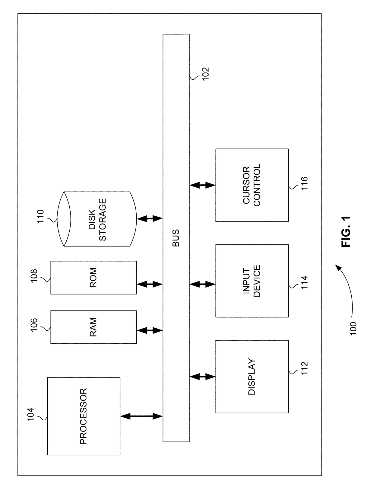
[0080]FIG. 1 is a block diagram that illustrates a computer system 100, upon which embodiments of the present teachings may be implemented. Computer system 100 includes a bus 102 or other communication mechanism for communicating information, and a processor 104 coupled with bus 102 for processing information. Computer system 100 also includes a memory 106, which can be a random access memory (RAM) or other dynamic storage device, coupled to bus 102 for storing instructions to be executed by processor 104. Memory 106 also may be used for storing temporary variables or other intermediate information during execution of instructions to be executed by processor 104. Computer system 100 further includes a read only memory (ROM) 108 or other static storage device coupled to bus 102 for storing static information and instructions for processor 104. A storage device 110, such as a magnetic disk or optical disk, is provided and coupled to bus 102 for storing infor...


PUM


Abstract

An ECG system identifies and annotates cardiac electrophysiological signals in an ECG waveform from harmonic waveforms. Electrical impulses are received from a beating heart. The electrical impulses are converted to an ECG waveform. The ECG waveform is converted to a frequency domain waveform, which, in turn, is separated into two or more different frequency domain waveforms, which, in turn, are converted into a plurality of time domain cardiac electrophysiological subwaveforms and discontinuity points between these subwaveforms. The plurality of subwaveforms and discontinuity points are compared to a database of subwaveforms and discontinuity points for normal and abnormal patients. At least one subwaveform or one or more discontinuity points are identified as a normal or abnormal electrophysiological signal of the ECG waveform from the comparison. The ECG waveform is displayed along with one or more markers at a location of the at least one subwaveform or one or more discontinuity points.

Description

CROSS-REFERENCE TO RELATED APPLICATION[0001]This application is a continuation in part of U.S. patent application Ser. No. 15 / 393,135, filed Dec. 28, 2016, which is a continuation in part of U.S. patent application Ser. No. 14 / 749,697, filed Jun. 25, 2015, now U.S. Pat. No. 9,538,930 (hereinafter the “'930 Patent”), which is a continuation in part of U.S. patent application Ser. No. 14 / 662,996, filed Mar. 19, 2015, now U.S. Pat. No. 9,339,204 (hereinafter the “'204 Patent”), which is a continuation of PCT Application No. PCT / US15 / 20828, filed Mar. 16, 2015, which claims the benefit of U.S. Provisional Patent Application Ser. No. 62 / 008,435, filed Jun. 5, 2014; this application also claims the benefit of U.S. Provisional Patent Application Ser. No. 62 / 463,662, filed Feb. 26, 2017; U.S. patent application Ser. No. application Ser. No. 15 / 393,135 claims the benefit of U.S. Provisional Patent Application Ser. No. 62 / 271,704, filed Dec. 28, 2015, and U.S. Provisional Patent Application S...

Claims


Application Information

Patent Timeline
Patent Type & Authority Applications(United States)
IPC IPC(8): A61B5/04A61B5/0468A61B5/00A61B5/0464A61B5/046A61B5/361A61B5/363A61B5/364
CPCA61B5/04012A61B5/0468A61B5/725A61B5/0464A61B5/046A61B5/7257A61B5/0408A61B5/316A61B5/25A61B5/364A61B5/363A61B5/361
Inventor CHEN, GUANGRENYANG, RONGJIANG, ZHONGNONG
Owner CHEN GUANGREN
Why Eureka
Try Eureka