Method of manufacturing a component

Inactive Publication Date: 2018-07-19
ROLLS ROYCE PLC
View PDF11 Cites 3 Cited by
  • Summary
  • Abstract
  • Description
  • Claims
  • Application Information

AI Technical Summary

Benefits of technology

[0009]The present disclosure seeks to provide an im

Problems solved by technology

Powder forming components has inherent difficulties, particularly in relation to producing net-shape or near-net-shape conditions of supply (COS).
This can mean that f

Method used


Image

  • Method of manufacturing a component
  • Method of manufacturing a component
  • Method of manufacturing a component

Examples


Example

DETAILED DESCRIPTION OF THE DRAWINGS AND EMBODIMENTS

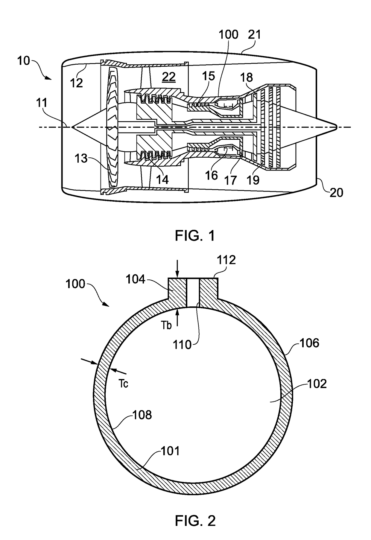
[0036]With reference to FIG. 1, a gas turbine engine is generally indicated at 10, having a principal and rotational axis 11. The engine 10 comprises, in axial flow series, an air intake 12, a propulsive fan 13, an intermediate pressure compressor 14, a high-pressure compressor 15, combustion equipment 16, a high-pressure turbine 17, an intermediate pressure turbine 18, a low-pressure turbine 19, and an exhaust nozzle 20. A nacelle 21 generally surrounds the engine 10 and defines both the intake 12 and the exhaust nozzle 20.

[0037]The gas turbine engine 10 works in the conventional manner so that air entering the intake 12 is accelerated by the fan 13 to produce two air flows: a first air flow into the intermediate pressure compressor 14 and a second air flow which passes through a bypass duct 22 to provide propulsive thrust. The intermediate pressure compressor 14 compresses the air flow directed into it before delivering that air ...


PUM

PropertyMeasurementUnit
Thicknessaaaaaaaaaa
Depthaaaaaaaaaa

Abstract

A method of manufacturing a component (100) having a main part (101) and a projecting feature (104,114), the method comprising providing a shaped void (210) corresponding to the component, locating a pre-formed element (214) in a feature region of the shaped void which corresponds to the projecting feature, locating powder (212) within the shaped void; and forming the element and the powder into the component such that the element creates at least a part of the projecting feature.

Description

CROSS-REFERENCE TO RELATED APPLICATION[0001]This application is based upon and claims the benefit of priority from British Patent Application No. 1700614.9 filed 13 Jan. 2017, the entire contents of which are incorporated herein.FIELD OF DISCLOSURE[0002]The present disclosure concerns a method of manufacturing a component and in particular, although not exclusively, a method of forming a component using hot isostatic pressing.BACKGROUND[0003]It is known to form manufacture components from powdered materials, such as powdered metals or ceramics. A number of methods are available to form solid components from powders, and the chosen method depends upon the required properties of the component and the available budget. For example, sintering is a cheaper and simpler method of forming a component from powder, whilst hot isostatic pressing (HIP) is more expensive and complex but forms a component having improved mechanical properties when compared to the same component formed by sinterin...

Claims


Application Information

Patent Timeline
IPC IPC(8): B22F7/06B22F3/15B22F5/00B29B11/12B29C43/00B29C43/18B28B3/00
CPCB22F7/064B22F3/15B22F5/008B29B11/12B29C43/006B29C43/18B28B3/003B29C2043/189B29L2031/748B22F3/1258B22F2998/10B22F2999/00B28B3/025B28B23/0068B29L2031/3076B22F5/00B22F7/06B22F7/08
Inventor MULCAIRE, THOMAS G.
Owner ROLLS ROYCE PLC
Why Eureka
Try Eureka