Device for winding a screen having a hinged wall attachment

a technology of hinged wall and winding device, which is applied in the direction of door/window protective device, building components, construction, etc., can solve the problems of not being able to transpose to a winder, and not always easy to access this wall

Active Publication Date: 2018-07-19
SOMFY ACTIVITES SA
View PDF23 Cites 6 Cited by
  • Summary
  • Abstract
  • Description
  • Claims
  • Application Information

AI Technical Summary

Problems solved by technology

However, access to this wall is not always easy when the winding device is fastened at a small distance from the lintel in the upper part of an opening in a building.
However, these solutions are not transposable to a winder whose ceils are positioned inside the winding tube.

Method used


Image

  • Device for winding a screen having a hinged wall attachment
  • Device for winding a screen having a hinged wall attachment
  • Device for winding a screen having a hinged wall attachment

Examples


second embodiment

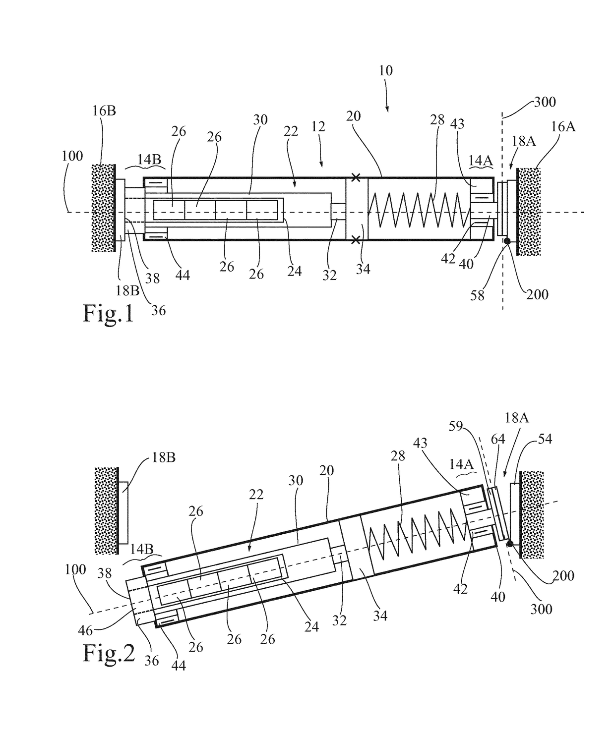
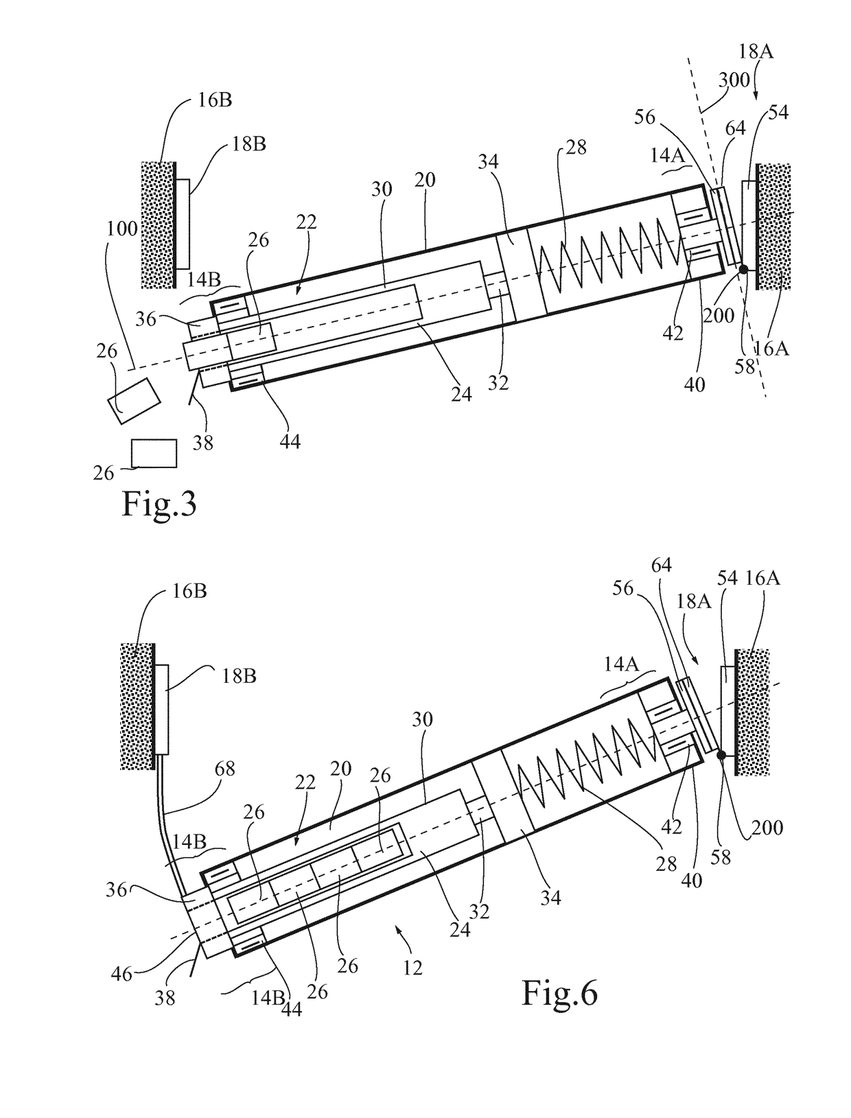
[0055]FIG. 6 shows a screen winding device 10 which differs from the preceding embodiment by the addition of a retractable support link 68 providing the connection between the second wall attachment 18B and the second end portion 14B of the tubular winder 12, to support the second portion 14B of the winder in a suspended position illustrated in FIG. 6. The retractable support link 68 can be flexible or rigid, telescoping or articulated, and may be secured to the second wall attachment 18B or the second end portion 14B.

[0056]The support link 68 may in particular be made up of a guide rail or may be a simple detachable link retaining the second end portion 14B in the suspended position to replace the battery cells. The installer thus no longer needs to maintain this end portion and may very easily change the battery cells (opening the battery ceil hatch, receiving battery ceils to be changed, performing the replacement and closing the hatch).

third embodiment

[0057]FIG. 7 illustrates the invention, which differs from the previous embodiments by the positioning of the compensating spring 28, one of the ends of which is fastened to the case 30 of the actuator 22 and the other end of which is fastened to the output shaft 32 of the actuator 22, for example in the manner described in document WO 03 / 083245.

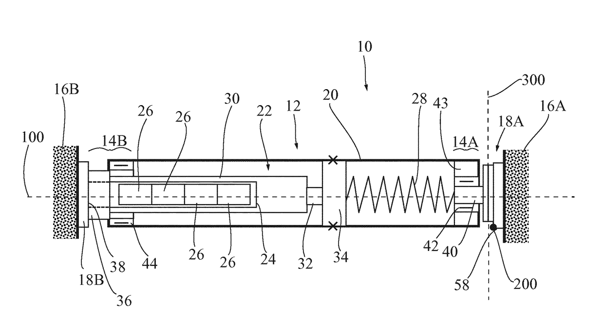
[0058]According to a fifth embodiment illustrated in FIG. 8, the output shaft 32 of the actuator 22 is part of the first end portion 14A of the tubular winder 12, and is fixed in rotation around the reference axis 100 relative to the first wall attachment 16A. The winding tube 20 is secured to a driving wheel 34 to which the head 36 of the actuator 22 is fastened. A housing box 24 for the batteries or battery cells 26 is also fastened to the inside of the winding tube 20, for example fastened on the driving wheel 34 or on another wheel 134 of the same type. The rotating assembly formed by the winding tube 20, the case 30 of the actuator 22 a...

sixth embodiment

[0060]FIGS. 9 to 11 show a winding device according to the invention, which, like the previous embodiments, includes a tubular winder 12, a first articulated wall attachment 18A and a second wall attachment 18B. The figures also show a screen 70 wound on the winding tube 20 of the tubular winder 12. In a known manner, the screen 70 is provided at its free end with a load bar 72, which moves with the screen 70 during the unwinding and winding thereof, and is able to assume an extreme winding position, illustrated in FIGS. 9 to 11, in particular for assembly, disassembly or maintenance operations of the equipment. In the case at hand, the load bar 72 in the extreme winding position is jammed abutting against a first stop 74A secured to the first wall attachment 18A and against a second stop 74B secured to the second wall attachment 18B. It is alternatively or cumulatively possible to provide other fastening or maintaining means for the load bar 72 in the extreme winding position, for ...


PUM


Abstract

The invention relates to a device for winding a screen (10) which comprises a tubular winder (12) defining a reference axis (100); a first wall attachment (18A) for fastening a first axial end portion (14A) of the tubular winder (12) to a first wall (16A) in a use position of the screen-winding device (10); and a second wall attachment (18B) for fastening a second axial end portion (14B) of the tubular winder (12) to a second wall (16B) in the use position of the screen-winding device (10). The first wall attachment (18A) comprises at least one tab (54) for fastening to the first wall (16A) and at least one first hinge (58) supported by the fastening tab (54) in order to guide a pivoting of the tubular winder (12) about a first axis of articulation (200) that does not intersect with the reference axis (100) and, in the use position, orthogonal to the reference axis (100). The first wall attachment (18A) comprises a second jointed hinge (66) supported by the fastening tab (54) in order to guide the first hinge (58) so as to rotate about a second axis of articulation (300) that does not intersect with the reference axis and is not parallel to the first axis of articulation (200).

Description

TECHNICAL FIELD OF THE INVENTION[0001]The invention relates to a device for winding a screen, and in particular a screen for closing off an opening in a building or a projection screen, and in particular, but not exclusively, a motorized winding device, and more specifically, but not exclusively, a motorized device having an onboard electrical energy reserve.BACKGROUND OF THE INVENTION[0002]In order to facilitate the replacement of battery cells for a screen winder, it has been proposed in document U.S. Pat. No. 6,371,192 to provide, in the winder, a housing closed by an access hatch situated on a planar upper wall of the box of the winder. However, access to this wall is not always easy when the winding device is fastened at a small distance from the lintel in the upper part of an opening in a building. It is then necessary to completely disassemble the winder to access the access hatch.[0003]To resolve this problem, it has been proposed in document US 2013 / 0153162 to fasten the bo...

Claims


Application Information

Patent Timeline
Patent Type & Authority Applications(United States)
IPC IPC(8): E06B9/50E06B9/44E06B9/72
CPCE06B9/50E06B9/44E06B9/72E06B9/174
Inventor LAGARDE, ERIC
Owner SOMFY ACTIVITES SA
Why Eureka
Try Eureka