
Temperature sensor

Active Publication Date: 2018-07-19
VALEO SYST DE CONTROLE MOTEUR
View PDF6 Cites 0 Cited by
  • Summary
  • Abstract
  • Description
  • Claims
  • Application Information

AI Technical Summary

Benefits of technology

The invention makes it easier to manufacture thermocouple wires because it eliminates the need to close the protective sheath on itself. This also makes it easier to remove the mineral insulator and hollow out the sheath.

Problems solved by technology

Such a manufacturing method is difficult to automate and currently involves delicate manual operations.

Method used


Image

  • Temperature sensor
  • Temperature sensor

Examples


Embodiment Construction

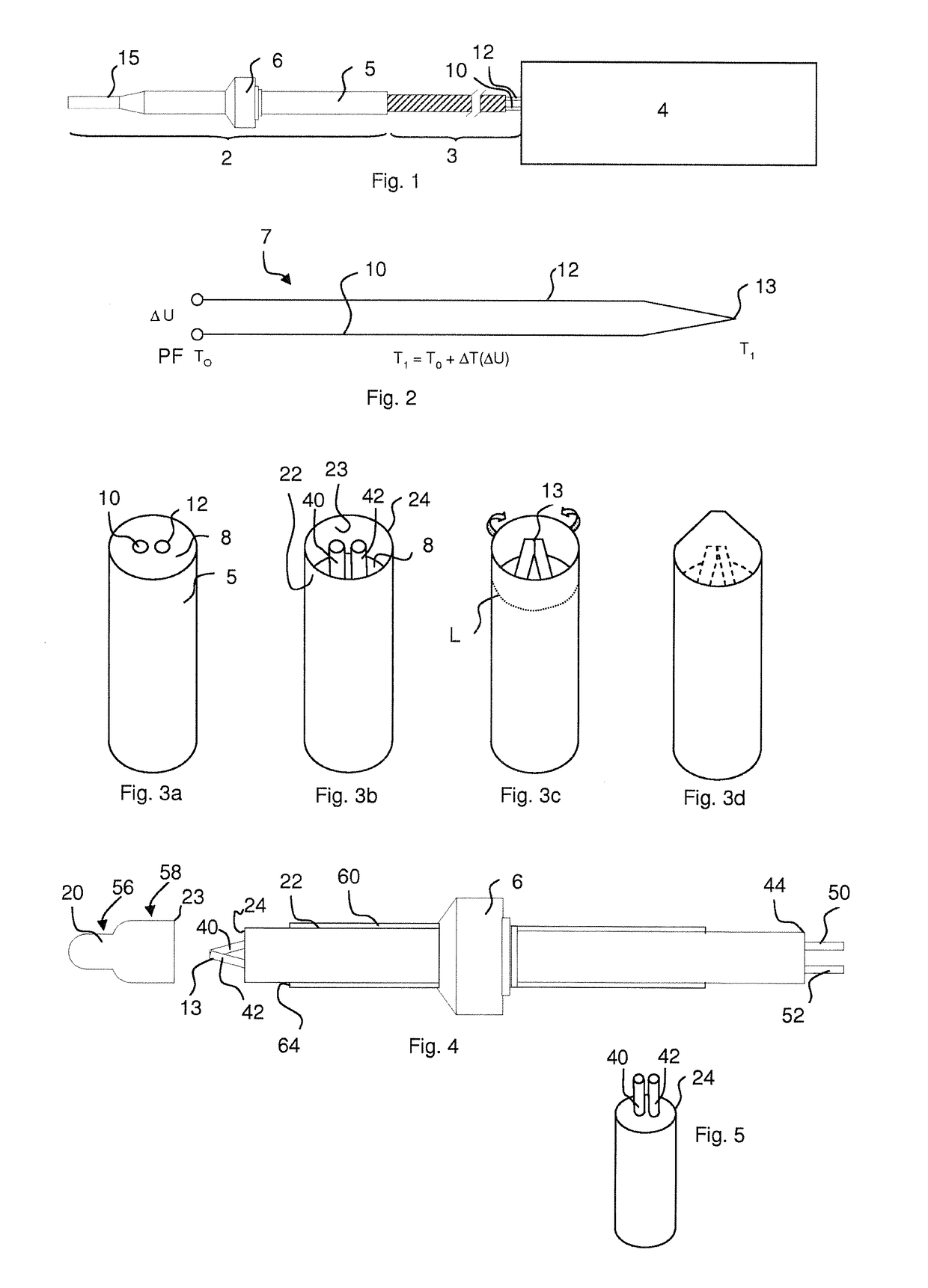
[0055]FIGS. 1 to 3 having been described in the preamble, we will now turn to FIG. 4.

[0056]Any mineral insulated cable of the prior art used to manufacture a sensor with a thermocouple can be implemented.

[0057]Preferably, the outer diameter of the protective sheath 5 is greater than 4 mm, preferably greater than or equal to 4.5 mm and / or less than 7 mm, preferably less than 6 mm.

[0058]The protective sheath can be made from an electrically conductive material.

[0059]The thermocouple wires can be flexible or rigid. Preferably, they have a substantially circular cross-section. Also preferably, the largest dimension and / or the smallest dimension of a cross-section of a thermocouple wire is greater than or equal to 0.2 and / or less than or equal to 1.

[0060]According to one embodiment of the invention, the pair of materials of the first and second thermocouple wires 10 and 12 is chosen from the group made up of the following pairs of materials: NiSil / NiCroSil.

[0061]The protruding parts 50 a...


PUM


Abstract

The invention relates to a method for manufacturing a temperature sensor with a thermocouple, which includes the following consecutive steps: a) manufacturing a cable with mineral insulator (14) including two thermocouple wires (10, 12) extending along the entire length of the cable with mineral insulator and embedded in a mineral insulator (8); b) stripping one of the ends of the cable with mineral insulator over a length of 2 to 20 mm, preferably less than 15 mm, preferably less than 10 mm, such as to expose the ends of the thermocouple wires; c) connecting the ends (40, 42) of the thermocouple wires thus exposed, such as to constitute a thermocouple hot spot (13); and d) attaching a cap (20) to said cable with mineral insulator so as to protect said hot spot.

Description

TECHNICAL FIELD[0001]The invention relates to a temperature sensor including a thermocouple intended to measure temperatures comprised between −40° C. and 1200° C., in particular in a heat engine unit of an automotive vehicle.BACKGROUND THE INVENTION[0002]As illustrated in FIG. 1, a temperature measuring device traditionally includes a temperature sensor 2 extended by an extension cable 3 making it possible to connect the temperature sensor to a measuring apparatus. The temperature sensor 2 traditionally includes a metal protective sheath 5 and a stop 6, mounted on the protective sheath 5 and adapted based on the targeted application.[0003]The measuring apparatus 4 is intended to interpret the electrical signal supplied by the temperature sensor 2 and sent via the extension cable 3. This interpretation is an evaluation of the temperature to which the end of the temperature sensor is subjected.[0004]Inside the protective sheath 5, the temperature sensor 2 traditionally includes a the...

Claims


Application Information

Patent Timeline
IPC IPC(8): G01K1/08G01K7/02
CPCG01K7/02G01K1/08G01K2205/04
Inventor DIXNEUF, OLIVIERZAKRZEWSKI, PIOTRGRAVAT, DENISGELEZ, NICOLAS
Owner VALEO SYST DE CONTROLE MOTEUR
Learn More