A Method For Manufacturing A Dental Prosthesis

Active Publication Date: 2016-06-30
DENTAL KNOWLEDGE
View PDF22 Cites 1 Cited by
  • Summary
  • Abstract
  • Description
  • Claims
  • Application Information

AI Technical Summary

Benefits of technology

[0011]An object of the invention is thus a manufacturing method of a dental prosth

Problems solved by technology

The procedure described above, besides being highly demanding in terms of high technical skills, is long and laborious and the patient is obliged to undergo several dent

Method used


Image

  • A Method For Manufacturing A Dental Prosthesis
  • A Method For Manufacturing A Dental Prosthesis
  • A Method For Manufacturing A Dental Prosthesis

Examples


Embodiment Construction

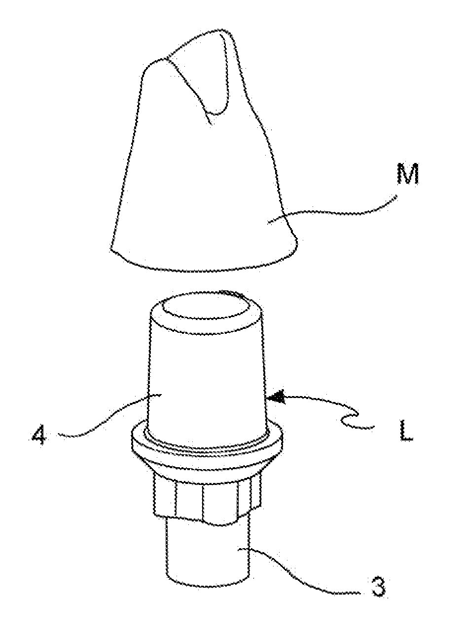
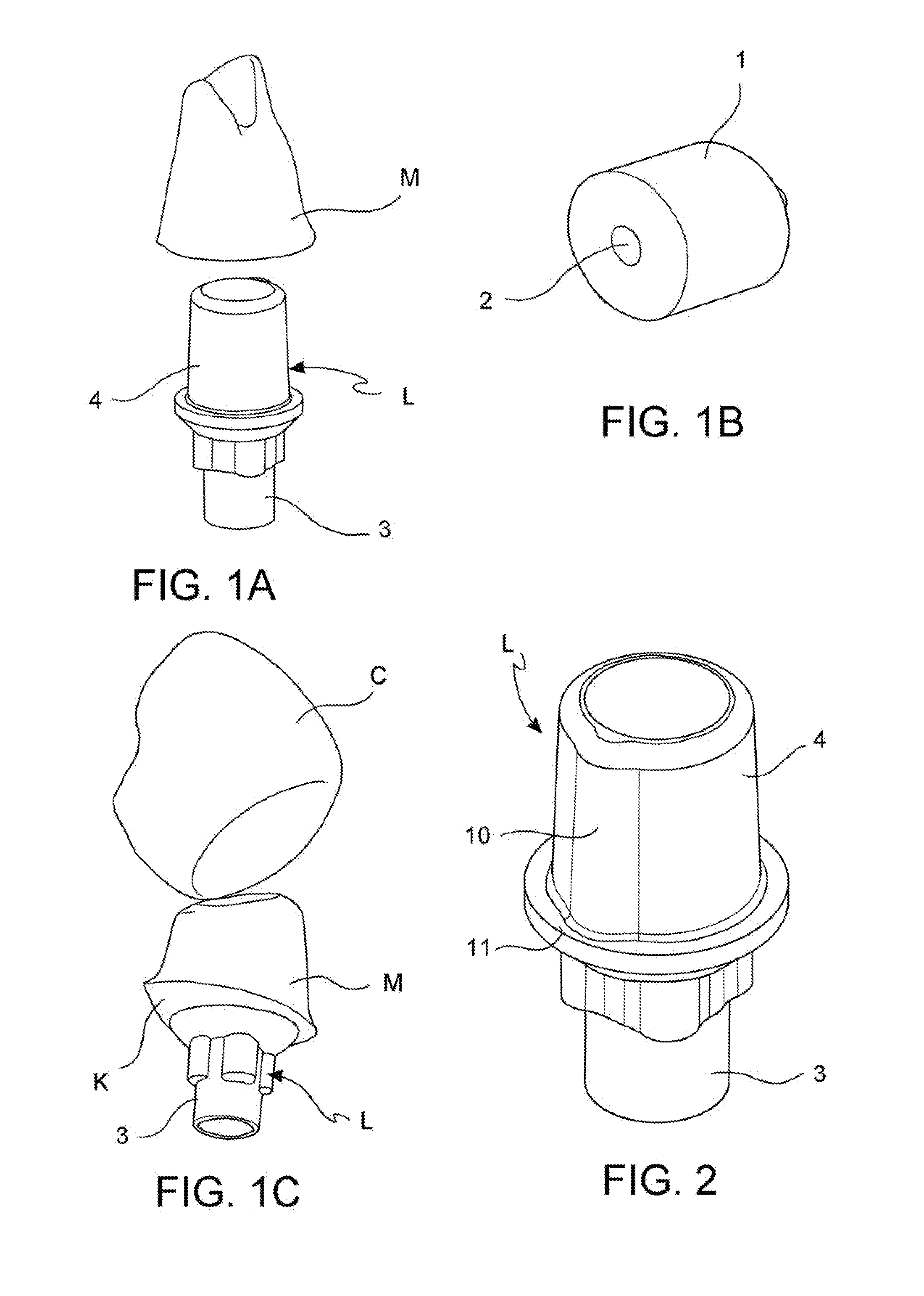
[0021]The invention concerns a manufacturing method of a dental prosthesis or a part thereof, that includes a milling step of a small block 1 made of a material suitable for dental uses, wherein the said block 1 is secured to a connection element for a dental implant.

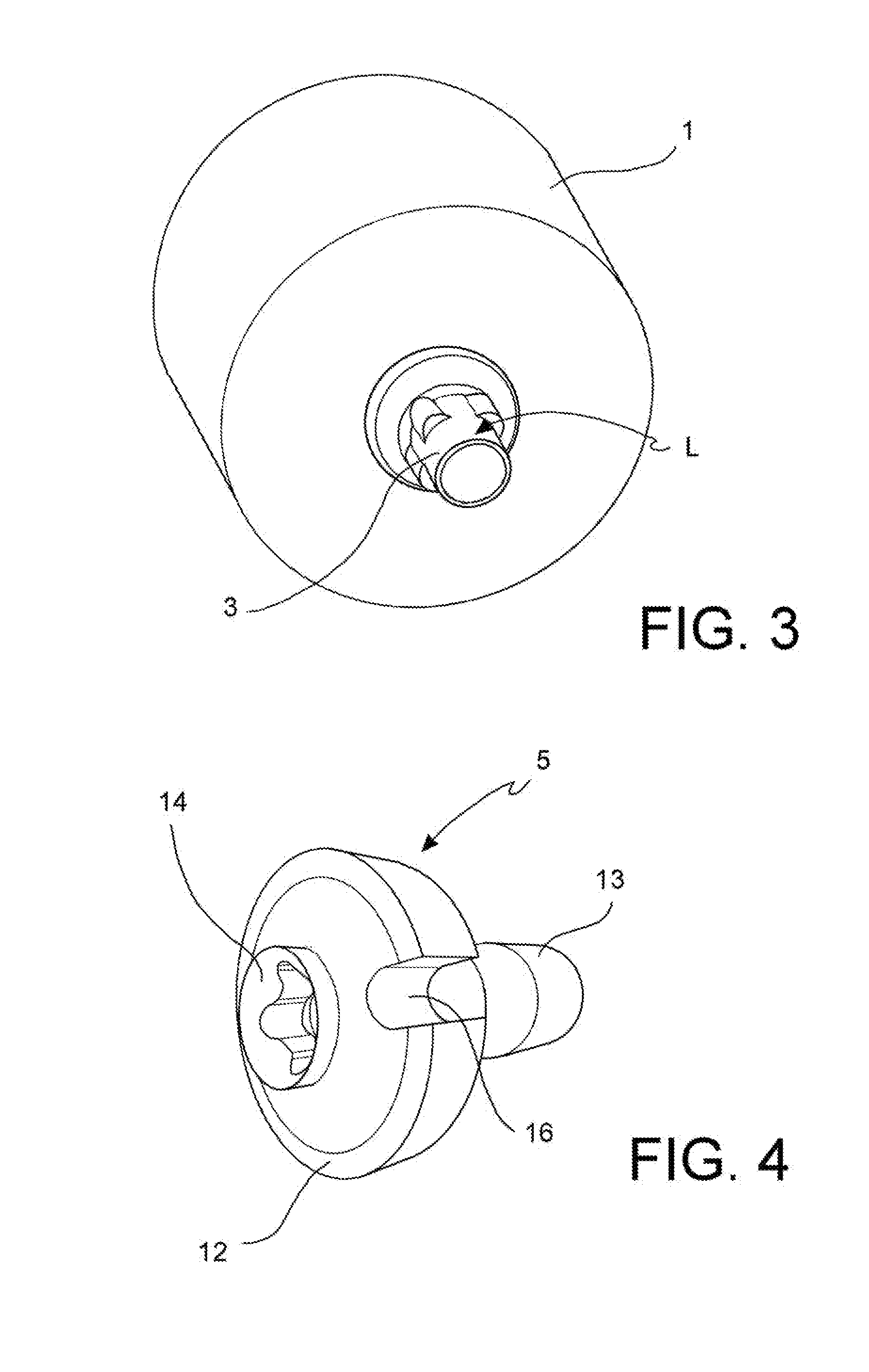
[0022]According to a preferred embodiment, the method of the invention includes the following steps:[0023]providing a milling machine 7 for dental uses,[0024]supplying a block 1 made of a material suitable for manufacturing dental prosthesis provided with a hole 2,[0025]providing a connection element L for a dental implant, the said connection element L having a first connection[0026]portion 3 to the said dental implant and a second connection portion 4 to a dental prosthesis,[0027]inserting the said second connection portion 4 of the connection element L into the hole 2 of the block 1 and securing the former to the latter, so as to form an assembly block 1—connection element L,[0028]providing a coupling member 5 betwee...


PUM

PropertyMeasurementUnit
Coloraaaaaaaaaa
Shapeaaaaaaaaaa

Abstract

This invention concerns a manufacturing method of a dental prosthesis, with specific reference to single-tooth prostheses. In particular, this invention deals with a manufacturing method a dental prosthesis or part thereof, that includes a milling step of a block (1) made of a material suitable for dental uses, where the aforementioned block (1) is secured to a connection device (L) with a dental implant.

Description

FIELD OF THE INVENTION[0001]This invention concerns a manufacturing method of a dental prosthesis, with specific reference to single-tooth prostheses.BACKGROUND ART[0002]A dental implant consists of a screw made of a biocompatible material, typically titanium, coated, if need be, with additional substances aimed at enhancing adhesion, osseointegration and resistence to bacterial attacks. The implant consists of an upper portion designed to emerge from the gingival arch that includes an internal thread to fix a connection device to which the dental crown will be secured.[0003]FIG. 1A shows one of the said connection devices L on which a stump M will be positioned, based on the conventional technique. The crown C will be then secured to the aforementioned stump M, as displayed in FIG. 1C. Both the stump M and the crown C are typically realized with materials that are suitable for dental uses. The procedure is first based on injecting some ceramic material within a mold, reproducing th...

Claims


Application Information

Patent Timeline
IPC IPC(8): A61C13/00B23Q3/10A61C13/083
CPCA61C13/0022B23Q3/103A61C13/083A61C8/005A61C13/0006
Inventor BERTAGNON, VALTER
Owner DENTAL KNOWLEDGE
Why Eureka
Try Eureka