System for tracking object, and camera assembly therefor

a technology for tracking objects and objects, applied in the field of tracking systems for falling objects, can solve the problems of generating loss, not taking into account the danger of falling objects, and conventional falling object detection systems, so as to prevent the occurrence of serious accidents, collect a falling object with high danger, and grasp the effect of the situation on-si

Active Publication Date: 2018-07-19
KOKUSA ELECTRIC CO LTD
View PDF9 Cites 18 Cited by
  • Summary
  • Abstract
  • Description
  • Claims
  • Application Information

AI Technical Summary

Benefits of technology

[0017]The disclosure provides a system for detecting and tracking an object, and camera assembly therefor. The system can quickly initialize a collection operation as to the object including a falling object on a road by considering the degree of danger as to the object, and make the grasp of the situation more effectively by cooperating with peripheral cameras.
[0024]According to one aspect of the disclosure, it is possible to collect a falling object having high degree of danger quickly, and to prevent the occurrence of serious accidents. Furthermore, when a falling object moves, tracking the object is performed in conjunction with the surrounding camera, so grasping the on-site situation can do effectively.

Problems solved by technology

Conventional falling object detection system has two problems.
First, when a falling object is detected, the degree of danger as to the falling object is not taken into consideration.
In a situation that degree of danger as to a falling object is not considered, there is a risk that delay of the collecting work as to the dangerous falling object may lead to serious accidents, furthermore, a loss that collecting an object which does not need to be collected may be generated.
A second problem is that each camera connected to a network has independently been performing detecting a falling object, respectively.
Furthermore, it takes time to grasp a situation that the detected falling object moved to a monitoring range of the other camera, for example, as a result that the detected falling object came in contact with a vehicle.

Method used


Image

  • System for tracking object, and camera assembly therefor
  • System for tracking object, and camera assembly therefor
  • System for tracking object, and camera assembly therefor

Examples


embodiment 1

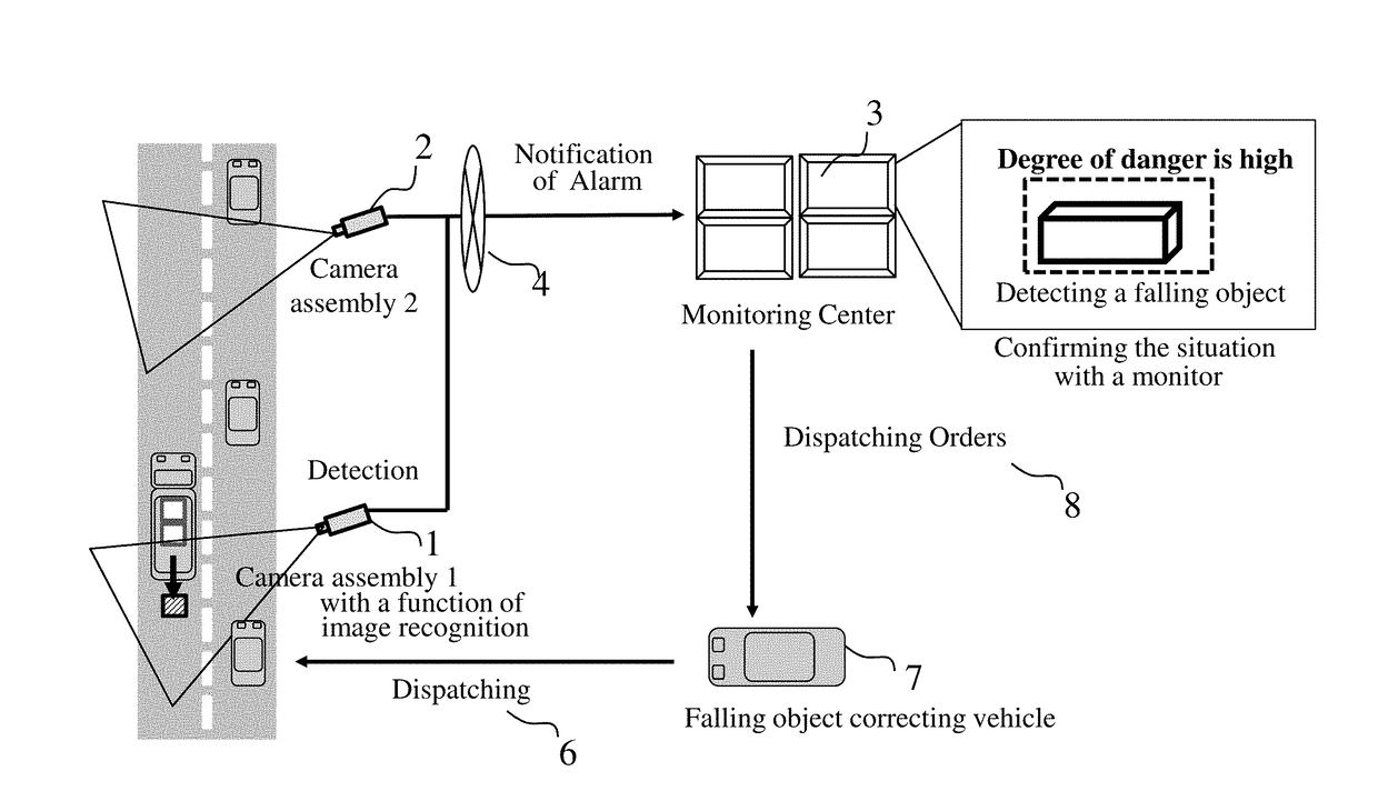
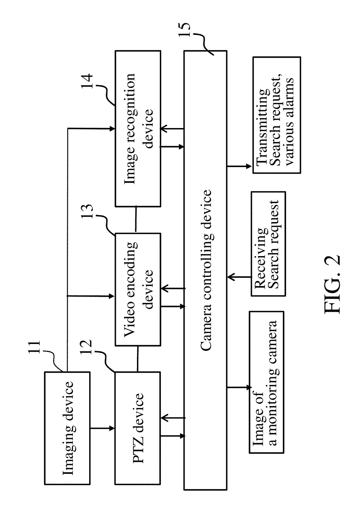
[0042]FIG. 1 is a diagrammatic illustration of a falling object detecting system according to a first embodiment. The falling object detecting system includes a plurality of camera assemblies, each camera assembly 1 arranged to along a road so as to photograph a monitoring area of the road, respectively, monitoring center 3 for monitoring the images received from the each camera assembly 1 and outputting instructions as necessary, and network 4 for connecting each camera assembly 1 with monitoring center 3. For example, two camera assemblies consisted of camera assembly 1 and camera assembly 2 are representative in the embodiment, a plurality of camera assemblies, more than two camera assemblies, can be arranged with an appropriate distance each other and located along the road. Each camera assembly 1 or camera assembly 2 may include an electrical panning and tilting head, an electrical zooming lens, or an image recognition device for detecting and tracking an object. Each camera as...


PUM


Abstract

Disclosed is an autonomous distributed system for detecting and tracking a falling object within a region being monitored by using a plurality of camera assemblies cooperating with each other, and disclosed is a camera assembly therefor. Each of the camera assembly, normally, operates in a falling object detecting mode, but, when detecting a falling object, shifts to a tracking mode. In the tracking mode, a degree of danger of the falling object is determined by referring to the size of the falling object in real space and the movement of a falling. In addition, when the falling object is further tracked and moved outside of the angle of view, a search request including information of the degree of danger as to the falling object is issued to surrounding camera assemblies, such that the multiple camera assemblies search for the falling object in cooperation.

Description

CROSS-REFERENCE TO RELATED APPLICATION[0001]The present application is a continuation-in-part application under 35 U.S.C § 111(a) of International Application No. PCT / JP2016 / 077237, filed Sep. 15, 2016, which claims priority to Japanese Patent Application No. 2015-184125, filed Sep. 17, 2015. The contents of these applications are incorporated herein by reference in their entirety.TECHNICAL FIELD[0002]The disclosure relates to a system for detecting and tracking an object, and a camera assembly therefor. The object includes a falling object on a road.BACKGROUND[0003]Conventionally, it is known that a system for detecting a falling object on a road by using image data output from a camera (see, for example, Patent Documents 1 to 5). In most of the conventional detecting systems, each camera arranged along the road has independently been performing an image processing for detecting a falling object on the road, respectively. When the camera has detected a falling object, the camera no...

Claims


Application Information

Patent Timeline
Patent Type & Authority Applications(United States)
IPC IPC(8): G06T7/292H04N5/232G08B25/00G06T7/62G06K9/00G06K9/66G08B29/18G06V10/40G06V10/56
CPCG06T7/292H04N5/23206H04N5/23296G08B25/006G06T7/62G06K9/00825G06K9/66G06K9/00798H04N5/23216G08B29/188G06T2207/10016G06T2207/30261G06T2207/30256G06T2207/20221G06K2209/21G08G1/0133G08G1/04H04N7/181G08B23/00G08B25/00G08G1/0116G08G1/0141G06T2207/10024G06T2207/30232G06T2207/30236G06T7/246G06V20/54G06V20/52G06V10/40G06V10/56G06V10/751G06V30/19173H04N23/661H04N23/61H04N23/634H04N23/69H04N23/695H04N23/90G06V20/584G06V20/588G06V2201/07G06F18/24H04N23/62
Inventor AGATA, YOSHIKISOGA, KUNIHIROYAMAGUCHI, MUNEAKIKOMIYA, YUICHIRO
Owner KOKUSA ELECTRIC CO LTD
Why Eureka
Try Eureka