Ear Shape Analysis Method, Ear Shape Analysis Device, and Ear Shape Model Generation Method

a technology of ear shape and analysis method, which is applied in the field of analyzing an ear shape, can solve the problems of considerable physical and psychological burdens on the listener, and the listener is unable to perceive the location of a sound image appropriately, and achieve the effect of reducing the probability of misestimating an ear shap

Active Publication Date: 2018-07-19
YAMAHA CORP
View PDF2 Cites 8 Cited by
  • Summary
  • Abstract
  • Description
  • Claims
  • Application Information

AI Technical Summary

Benefits of technology

[0006]In view of the above circumstances, an object of the present invention is to reduce a probability of misestimating an ear shape used in calculating head-related transfer functions.

Problems solved by technology

However, use of a dummy head for the calculation involves a problem in that the listener is unable to perceive a location of a sound image appropriately if the shape of the head of the listener and that of the dummy head do not match each other.
Measuring a head-related transfer function directly from the head of the listener also involves a problem in that considerable physical and psychological burdens are imposed on the listener during measurement.

Method used


Image

  • Ear Shape Analysis Method, Ear Shape Analysis Device, and Ear Shape Model Generation Method
  • Ear Shape Analysis Method, Ear Shape Analysis Device, and Ear Shape Model Generation Method
  • Ear Shape Analysis Method, Ear Shape Analysis Device, and Ear Shape Model Generation Method

Examples


first embodiment

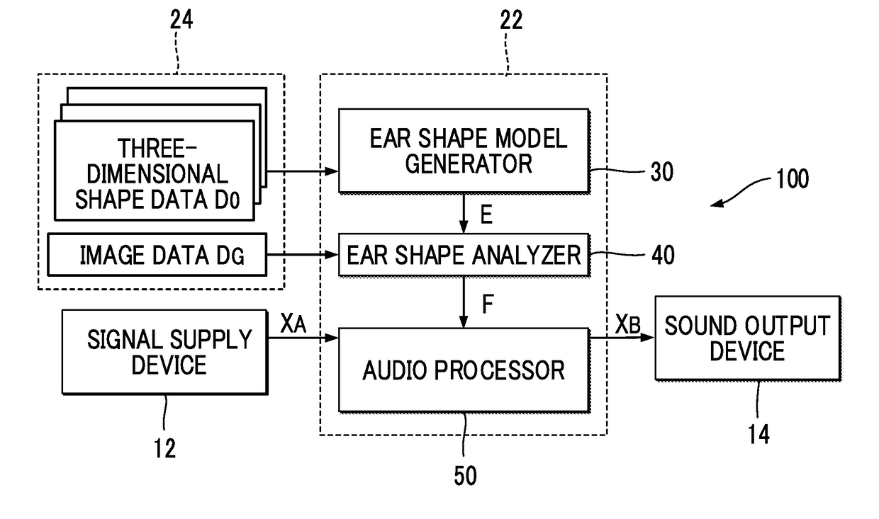
[0032]FIG. 1 is a block diagram showing a configuration of an audio processing device 100 according to a first embodiment of the present invention. As shown in FIG. 1, a signal supply device 12 and a sound output device 14 are connected to the audio processing device 100 of the first embodiment. The signal supply device 12 supplies an audio signal XA representing a sound, such as a voice and a music sound, to the audio processing device 100. Specific examples of the signal supply device 12 include: a sound receiving device that receives a sound in the surroundings to generate an audio signal XA; and a playback device that acquires an audio signal XA from a recording medium (either portable or in-built) and supplies the same to the audio processing device 100.

[0033]The audio processing device 100 is a signal processing device that generates an audio signal XB by applying audio processing to the audio signal XA supplied from the signal supply device 12. The audio signal XB is a stereo...

second embodiment

[0072]A second embodiment of the present invention is described below. In the different embodiments described below, elements having substantially the same actions or functions as those in the first embodiment will be denoted by the same reference symbols as those used in the description of the first embodiment, and detailed description thereof will be omitted as appropriate.

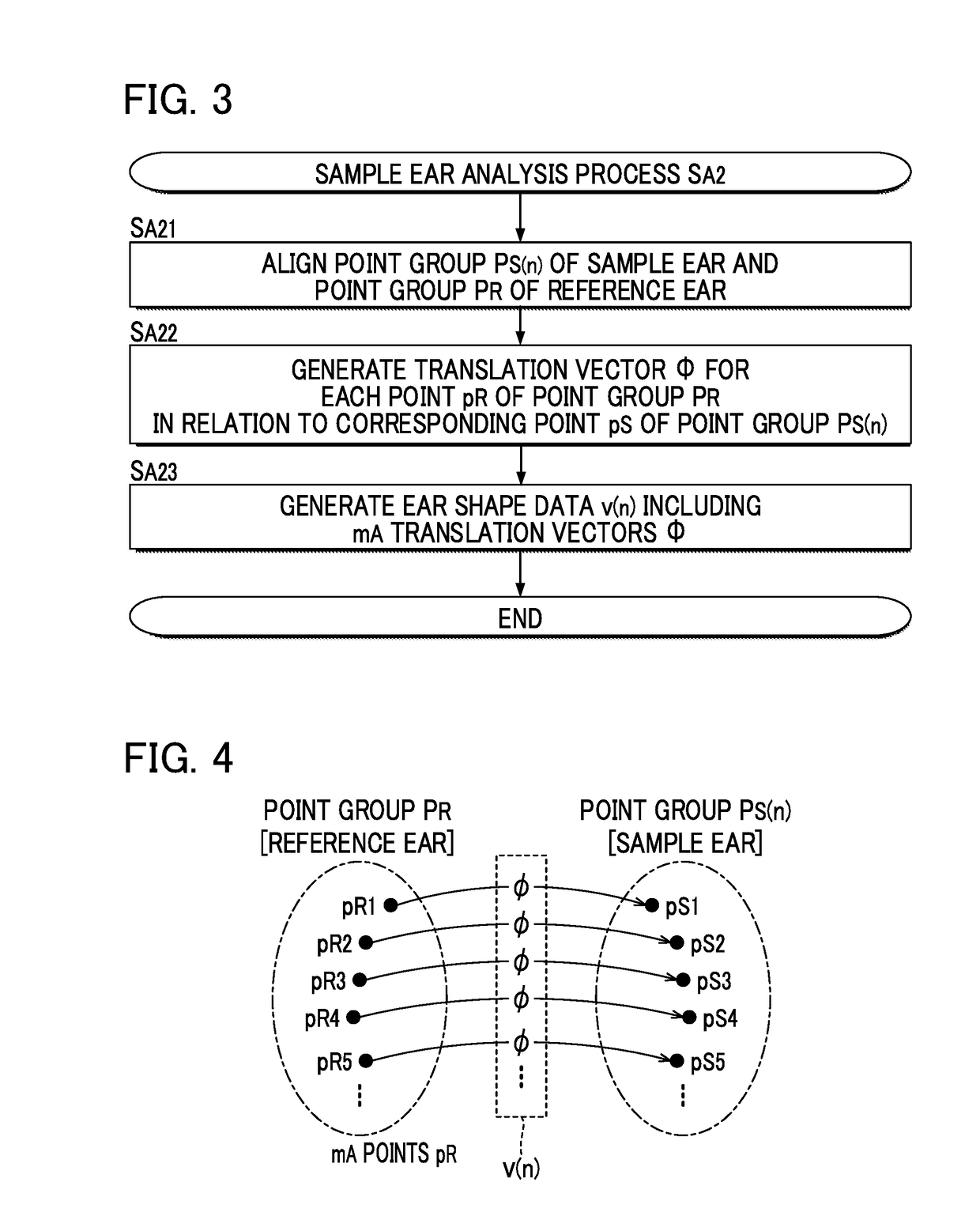
[0073]In the sample ear analysis process SA2 (SA22) in the first embodiment, a translation vector φ is calculated for every point pR of the point group PR of the reference ear, in relation to each corresponding point pS of a sample ear. In the second embodiment, a translation vector φ is calculated for each of mA points pR constituting a part (hereinafter, “first group”) of the point group PR of the reference ear, in relation to each corresponding point pS of a sample ear. In other words, while in the first embodiment the total number of the points pR constituting the point group PR of the reference ear is expre...

third embodiment

[0080]In the first embodiment, the statistics processor 36 generates a transformation matrix W with M rows and M columns. A statistics processor 36 of the third embodiment removes (a) prescribed row(s) from the lower rows of the transformation matrix W with M rows and M columns (that is, (a) prescribed row(s) corresponding to small eigenvalues), the transformation matrix W having been generated by performing principal component analysis on N ear shape data v(1) to v(N), and generates an ear shape model E including a transformation matrix W′ that has been obtained by the removal and has M′ rows and M columns (here, M′36 deletes (M−M′) rows from the (M′+1) th row to the Mth row in the matrix with M rows and M columns generated by the principal component analysis, and thereby obtains the transformation matrix W′ with M′ rows and M columns. Elements of rows from the first row to the M'th row are the same between the transformation matrix W and the transformation matrix W′.

[0081]An ear s...


PUM


Abstract

An ear shape analysis method implemented by a computer includes generating a first ear shape data set by applying a first principal component weight vector to an ear shape model reflecting statistical tendencies of three-dimensional shapes of ears; and identifying from the generated first ear shape data set an estimated three-dimensional shape of a target ear corresponding to a target ear image represented by image data.

Description

BACKGROUND OF THE INVENTIONField of the Invention[0001]The present invention relates to a technology for analyzing an ear shape that is used in calculating head-related transfer functions.Description of the Related Art[0002]Reproducing an audio signal representing a sound with head-related transfer functions convolved therein (binaural playback) allows a listener to perceive a sound field with a realistic feeling, in which sound field a location of a sound image can be clearly perceived. Head-related transfer functions may for instance be calculated from a sound recorded at the ear holes of either the head of a listener or a dummy head of a given shape. However, use of a dummy head for the calculation involves a problem in that the listener is unable to perceive a location of a sound image appropriately if the shape of the head of the listener and that of the dummy head do not match each other. Measuring a head-related transfer function directly from the head of the listener also in...

Claims


Application Information

Patent Timeline
Patent Type & Authority Applications(United States)
IPC IPC(8): G06T7/60A61B5/107G06K9/00
CPCG06T7/60A61B5/1077A61B5/1079G06K9/00214A61B2503/12G01B11/24G06T2207/30196H04S7/303H04S2420/01G06T17/00A61B2576/02A61B5/0077G06T7/149G06T2207/20084G06T2207/20081G06T2207/30201A61B5/107G06T7/00G06T19/20G06V20/653
Inventor KANEKO, SHOKEN
Owner YAMAHA CORP
Why Eureka
Try Eureka