
Connector

Active Publication Date: 2018-07-19
YAZAKI CORP
View PDF0 Cites 0 Cited by
  • Summary
  • Abstract
  • Description
  • Claims
  • Application Information

AI Technical Summary

Benefits of technology

The present invention relates to a connector for joining two tubes or pipes. The connector has a retainer insertion opening that is recessed in the opposite direction of fitting, preventing the mating connector from bumping into the opening inner-edge surface during fitting. This prevents damage to the connectors and reduces the workload of the operator. Additionally, the connector may also include a fitting assist lever for additional force during fitting, further reducing the workload and preventing damage.

Problems solved by technology

As a result, the bumping may become an obstacle to a fitting operation of the connector to the mating connector.

Method used


Image

  • Connector
  • Connector
  • Connector

Examples


Embodiment Construction

[0029]Hereinafter, a preferred embodiment of a connector according to the present invention will be described with reference to the drawings.

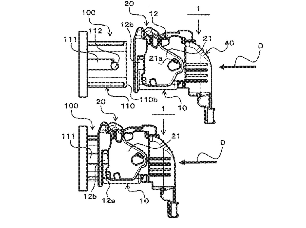
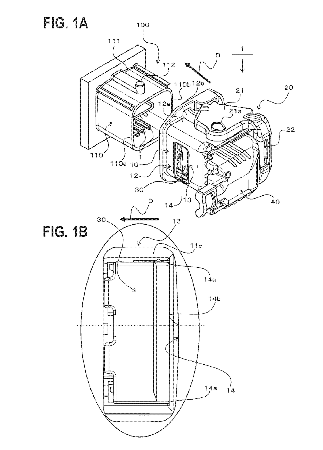
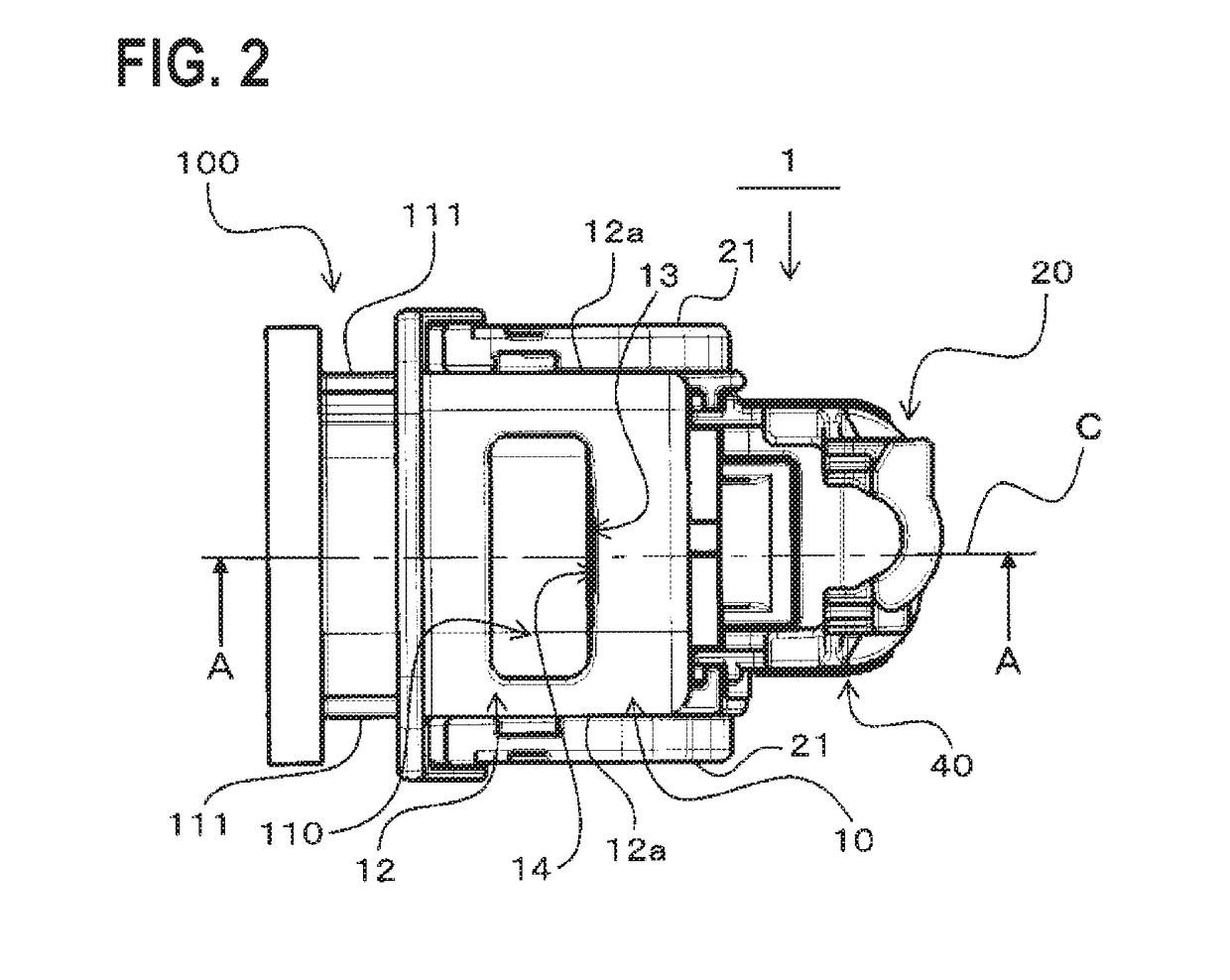
[0030]FIG. 1A is a perspective view illustrating a connector 1 according to an embodiment of the present invention and is a perspective view illustrating a mating connector 100 which is fitted into the connector 1, and FIG. 1B is an enlarged view illustrating the vicinity of a retainer insertion opening 13 of the connector 1 illustrated in FIG. 1A. FIG. 2 is a view illustrating the connector 1 in the middle of fitting to the mating connector 100 when viewed from a side of the retainer insertion opening 13. FIG. 3A is a sectional view illustrating the connector in the middle of fitting to the mating connector 100 taken along a line A-A illustrated in FIG. 2, and FIG. 3B is an enlarged view illustrating the vicinity of the retainer insertion opening 13 of the connector 1 illustrated in FIG. 3A. FIG. 4A is a view illustrating the retainer insertio...


PUM


Abstract

A connector having a connector housing, the connector includes a columnar terminal accommodating portion that is provided with a terminal accommodating chamber accommodating terminals therein and a hood portion that surrounds an outer circumferential surface of the terminal accommodating portion to have a gap between the hood portion and the outer circumferential surface so that a fitting tube of a mating connector is fitted into the gap, and is formed with a retainer insertion opening serving as an insertion port of a retainer locking the terminals in the terminal accommodating chamber. In the connector, the retainer insertion opening has an opening inner-edge surface facings in a fitting direction toward the mating connector, and the opening inner-edge surface is recessed in a direction opposite to the fitting direction and a center part of the opening inner-edge surface is most recessed.

Description

CROSS REFERENCE TO RELATED APPLICATION[0001]This application is based on Japanese Patent Application No. 2017-003977 filed on Jan. 13, 2017, the contents of which are incorporated herein by reference.BACKGROUND1. Technical Field[0002]The present invention relates to a connector including a hood portion in which a retainer insertion opening serving as an insertion port of a retainer is formed.2. Background Art[0003]In the related art, as a connector provided with a waterproof structure, there is known a connector including a connector housing provided with a columnar terminal accommodating portion in which a terminal accommodating chamber for receiving a terminal is formed, and a hood portion surrounding an outer circumferential surface of the terminal accommodating portion while having a gap between the hood portion and the outer circumferential surface so that a fitting tube of a mating connector is fitted into the gap.[0004]For example, JP-A-2002-329554 discloses a connector forme...

Claims


Application Information

Patent Timeline
IPC IPC(8): H01R13/629
CPCH01R13/4361H01R13/62938H01R13/5219H01R13/502H01R13/631
Inventor SHIMIZU, TOMOHIKO
Owner YAZAKI CORP
Learn More