
Light guiding plate, method of manufacturing thereof and backlight module with light guiding plate

a technology of light guiding plate and backlight module, which is applied in the direction of optical light guide, identification means, instruments, etc., can solve the problems of affecting the transparent effect of the transparent display, difficult workmanship and a shorter working life, and the inconvenience and defect of existing transparent displays, so as to improve the display effect and improve the transparency. , the effect of adjusting flexibility

Inactive Publication Date: 2018-07-26
CHUNGHWA PICTURE TUBES LTD +1
View PDF3 Cites 0 Cited by
  • Summary
  • Abstract
  • Description
  • Claims
  • Application Information

AI Technical Summary

Benefits of technology

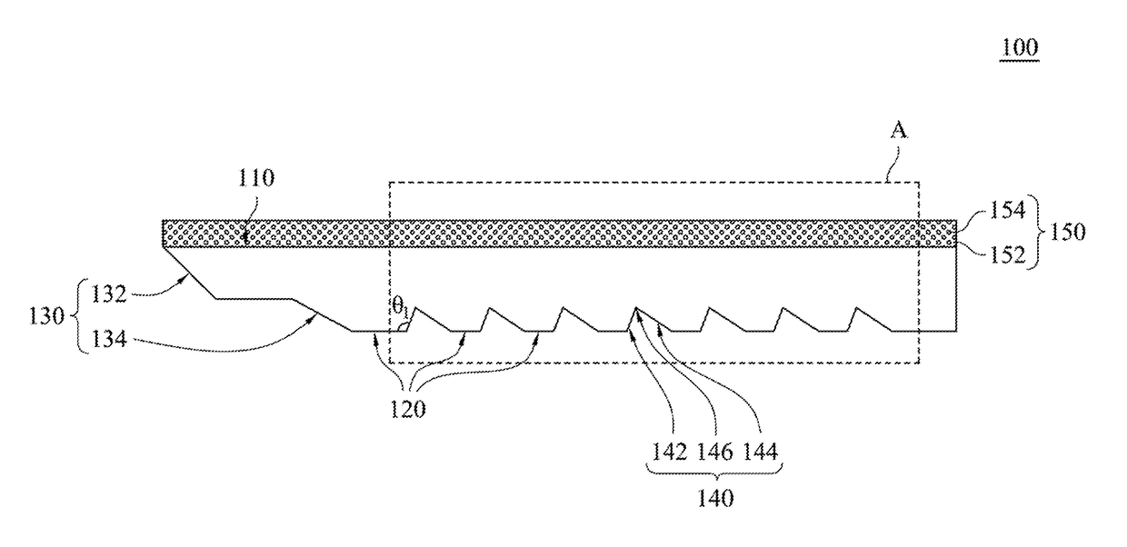
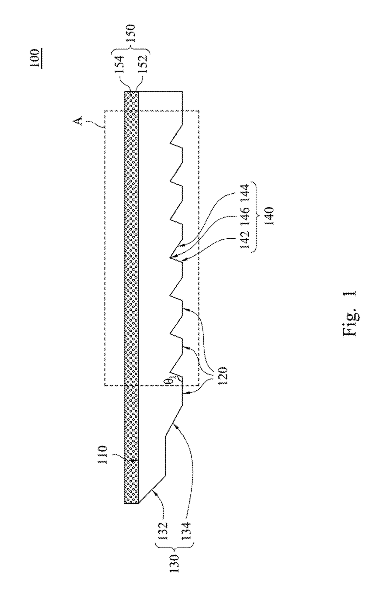
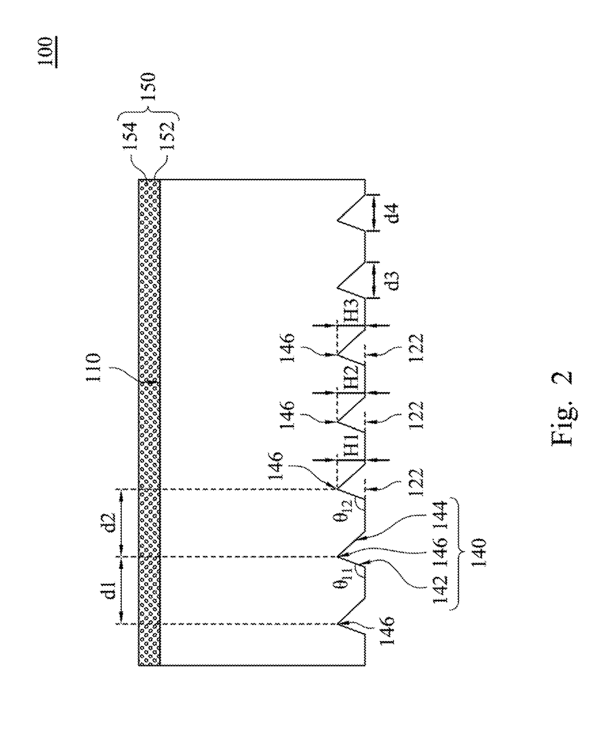
The present patent provides a light guiding plate with improved clarity and flexibility. The plate has trench structures on its surface opposite to the light emitting surface, which allow light to enter the plate and leave it after refracting at the structures. The light is also scattered by a layer on the light emitting surface before leaving. By adjusting the angle between the surface of the trench structures and the surface of the plate, various optical effects can be achieved. This design improves display quality and reduces the brightness required for a backlight module.

Problems solved by technology

However, the organic light emitting diodes are of a high cost, difficult workmanship and a shorter working life.
Moreover, the transparent effect of the transparent display will be affected.
Therefore, the existing transparent displays still have inconvenience and defect, which should be improved.

Method used


Image

  • Light guiding plate, method of manufacturing thereof and backlight module with light guiding plate
  • Light guiding plate, method of manufacturing thereof and backlight module with light guiding plate
  • Light guiding plate, method of manufacturing thereof and backlight module with light guiding plate

Examples


Embodiment Construction

[0033]Drawings will be used below to disclose embodiments of the present disclosure. For the sake of clear illustration, many practical details will be explained together in the description below. However, it is appreciated that the practical details should not be used to limit the claimed scope. In other words, in some embodiments of the present disclosure, the practical details are not essential. Moreover, for the sake of drawing simplification, some customary structures and elements in the drawings will be schematically shown in a simplified way. Wherever possible, the same reference numbers are used in the drawings and the description to refer to the same or like parts.

[0034]Unless otherwise defined, all terms (including technical and scientific terms) used herein have the same meanings as commonly understood by one of ordinary skill in the art to which this disclosure belongs. It will be further understood that terms, such as those defined in commonly used dictionaries, should ...


PUM


Abstract

A light guiding plate includes a light emitting surface, a structural surface, a light incident surface and a plurality of trench structures. The structural surface is opposite to the light emitting surface. The light incident surface connects between the light emitting surface and the structural surface. The trench structures are formed at intervals on the structural surface. Each of the trench structures includes a first surface and a second surface. The first surface connects with the structural surface. A first angle included between the first surface and the structural surface ranges from 110 degrees to 130 degrees. The second surface connects with the structural surface. The second surface connects with the first surface to form a trench axis. The first surface of each of the trench structures is closer to the light incident surface relative to the corresponding second surface.

Description

RELATED APPLICATIONS[0001]This application claims priority to Chinese Application Serial Number 201710041341.7, filed Jan. 20, 2017, which is herein incorporated by reference.BACKGROUNDTechnical Field[0002]The present disclosure relates to light guiding plates of high transparency. More particularly, the present disclosure relates to flexible transparent light guiding plates.Description of Related Art[0003]The commonly seen transparent displays have various usages and appearances. For example, some transparent displays allow the user to see the images at the back of the transparent displays when the transparent displays are in the sleeping mode. The transparent displays in the market can be roughly classified into two types. One type is transparent displays adopting organic light emitting diodes (OLED). However, the organic light emitting diodes are of a high cost, difficult workmanship and a shorter working life. Another type is transparent displays adopting thin film transistor pa...

Claims


Application Information

Patent Timeline
Patent Type & Authority Applications(United States)
IPC IPC(8): F21V8/00
CPCG02B6/0038G02B6/0051G02B6/002G02B6/0065G02B6/0031G02B6/0036G09F9/00
Inventor CHIU, CHUANG-HUNGCHIEN, CHAO-HENGCHEN, YUEH-HAOCHIEN, WEI-CHENG
Owner CHUNGHWA PICTURE TUBES LTD
Learn More