Pneumatic adjustable sanding device

a sanding device and pneumatic adjustment technology, applied in metal-working equipment, portable grinding machines, manufacturing tools, etc., can solve problems such as fairly complex mechanisms

Inactive Publication Date: 2009-05-14
CARBALLO EDGAR
View PDF10 Cites 2 Cited by
  • Summary
  • Abstract
  • Description
  • Claims
  • Application Information

AI Technical Summary

Benefits of technology

[0007]The present invention overcomes the disadvantages of the prior art by providing an attachment for an oscillatory sanding or abrading device which has an elongated flexible support member for supporting the sanding or abrading material. The initial radius of curvature of the flexible support member may be adjusted by a pneumatic adjustment mechanism. An opposing pair of generally cylindrical bladders are disposed proximate end portions of the flexible support member, the bladders being releasably attached between the underside of the abrading device and the support member. Adjustment of the initial radius of curvature of the flexible support is accomplished by selectively inflating one or both of the bladders. The radius of curvature of the flexible support member during the sanding process is then a function of the applied pressure and the inflation of the bladders. The device allows for virtually infinitely varying adjustments of the curvature of the flexible sheet and the attached abrading sheet.
[0012]It is an object of the invention to provide a new and improved attachment for sanding and abrading devices having springs of varying spring constants for adjusting the flexibility of the support mechanism for the sanding and abrading material.
[0014]Finally, it is a general object of the invention to provide improved elements and arrangements thereof in an apparatus for the purposes described which is inexpensive, dependable and fully effective in accomplishing its intended purposes.

Problems solved by technology

The adjustment means is relatively rigid and has a fairly complex mechanism, including a pair of screw adjusted journals which may be selectively raised, lowered, or spaced to adjust the curvature of the supporting base.

Method used


Image

  • Pneumatic adjustable sanding device
  • Pneumatic adjustable sanding device
  • Pneumatic adjustable sanding device

Examples


Embodiment Construction

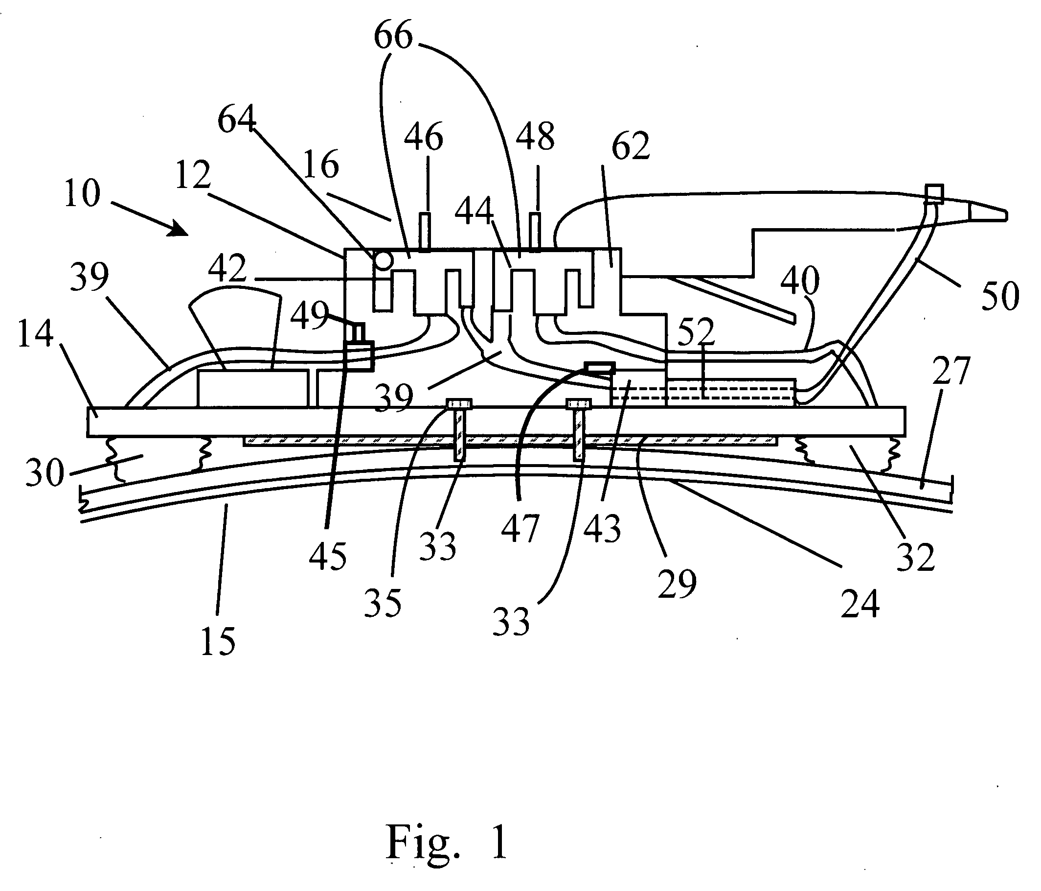
[0022]Referring now to FIGS. 1-4C, a sanding and abrading machine attachment integrated with a standard sanding and abrading machine is shown. The attachment, generally indicated by the numeral 10, is adapted for use with a handheld pneumatic or other powered sander 12 having a flat bed 14 which is moved in a longitudinal or orbital path at a relatively high speed. These sanders 12 typically have only a single flat bed 14 with means such as clamps etc. for selectively releasing / securing strips of sanding or abrading material to be applied to a workpiece. Sanding or abrading contoured surfaces is typically done with some difficulty even by professionals, the results obtained thereby are not always satisfactory, and even in the event they are, much time is consumed in the process. To that end, the attachment 10 of the present invention is provided to facilitate sanding of contoured surfaces with superior results while minimizing the time spent by the worker.

[0023]The attachment 10 inc...


PUM


Abstract

An attachment for an oscillatory sanding or abrading device has a pair of flexible support members for supporting the sanding or abrading material. The initial radius of curvature of the flexible support member may be adjusted by a pneumatic adjustment mechanism. An opposing pair of generally cylindrical bladders are disposed proximate end portions of the flexible support member, the bladders being releasably attached between the underside of the abrading device and the support member. Adjustment of the initial radius of curvature of the flexible support is accomplished by selectively inflating one or both of the bladders. The radius of curvature of the flexible support member during the sanding process is then a function of the applied pressure or inflation of the bladders. The device allows for virtually infinitely varying adjustments of the curvature of the flexible sheet and the attached abrading sheet.

Description

BACKGROUND OF THE INVENTION[0001]The present invention relates to sanding and abrading devices. More particularly, it relates to an improved attachment for an automatic pneumatically powered sanding and abrading device which allows for adjustably sanding and abrading contoured surfaces.STATEMENT OF THE PRIOR ART[0002]Various types of sanders and abrading devices have been devised which allow for sanding and abrading contoured surfaces. These types of device are especially useful in the automotive body repair industry, as recent card designs have featured highly contoured, aerodynamic body designs. The majority of these devices are either manual devices or are designed to work with specialized actuators.[0003]U.S. Pat. No. 5,700,187 issued to Balbi discloses a tool for sanding contoured surfaces having means for adjustably controlling the shape of the base to which the sanding material is applied. The adjustment means is relatively rigid and has a fairly complex mechanism, including ...

Claims


Application Information

Patent Timeline
Patent Type & Authority Applications(United States)
IPC IPC(8): B24B23/00
CPCB24B23/043B24B19/26
Inventor CARBALLO, EDGAR
Owner CARBALLO EDGAR
Why Eureka
Try Eureka