Liquid-cooling heat dissipation device

a heat dissipation device and liquid cooling technology, which is applied in the direction of cooling/ventilation/heating modification, electrical apparatus, semiconductor/solid-state device details, etc., can solve the problems of unsatisfactory heat dissipation efficiency and drawbacks of conventional liquid-cooling heat dissipation devices, and achieves improved liquid-cooling heat dissipation, improved heat dissipation structure, and gradual reduction of the vertical height of the inpu

Inactive Publication Date: 2018-07-26
AURAS TECH
View PDF30 Cites 13 Cited by
  • Summary
  • Abstract
  • Description
  • Claims
  • Application Information

AI Technical Summary

Benefits of technology

[0003]For solving the drawbacks of the conventional technology, the present invention provides an improved liquid-cooling heat dissipation device. The liquid-cooling heat dissipation device includes a thermally conductive base and a covering structure. An input chamber and an output chamber are defined by the thermally conductive base and the covering structure collaboratively. The vertical height of the input chamber is gradually decreased in the direction from an entrance toward an exit. Since the liquid entering the input chamber is guided to the heat dissipation structure, the contact area between the liquid and the heat dissipation structure is increased. Moreover, the liquid-cooling heat dissipation device further comprises a guiding plate between the thermally conductive base and the covering structure collaboratively. Due to the guiding plate, the liquid is precisely guided to strike the heat dissipation structure. Consequently, the cooling efficacy is enhanced.

Problems solved by technology

However, the conventional liquid-cooling heat dissipation device still has some drawbacks.
Under this circumstance, the heat dissipating efficiency is usually unsatisfied.

Method used


Image

  • Liquid-cooling heat dissipation device
  • Liquid-cooling heat dissipation device
  • Liquid-cooling heat dissipation device

Examples


first embodiment

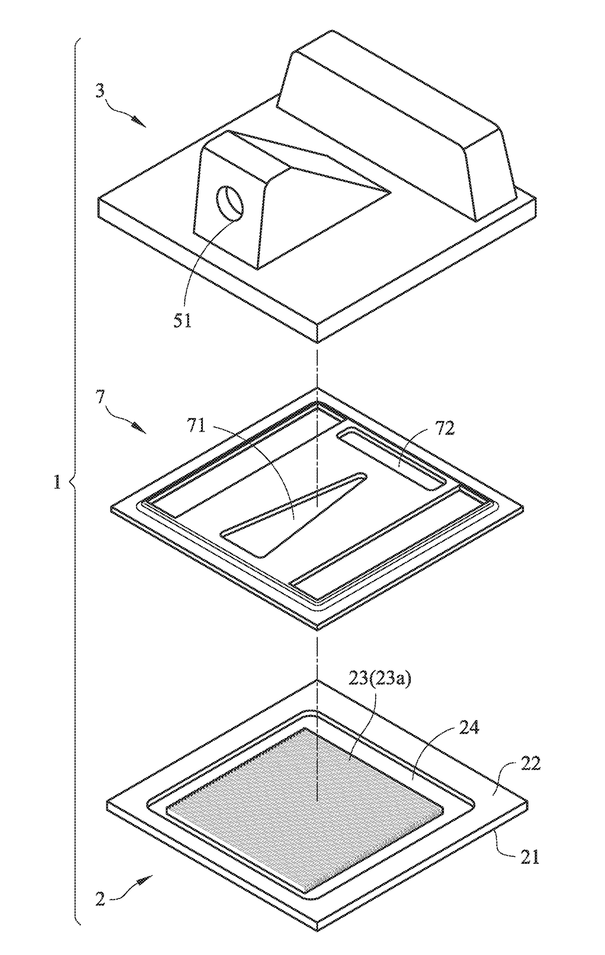
[0044]Like the first embodiment, the input chamber 5 has a tapered space for guiding the liquid toward the heat dissipation structure 23. Especially, the guiding plate 7 is arranged between the thermally conductive base 2 and the covering structure 3. By the guiding plate 7, the liquid in the input chamber 5 is guided to the heat dissipation structure 23 more intensively. Especially, the liquid is guided to a middle region of the heat dissipation structure 23 or any other region of the heat dissipation structure 23 that requires the liquid to flow through. In this embodiment, the guiding plate 7 comprises an inlet 71 and an outlet 72. The inlet 71 is disposed under the input chamber 5. The outlet 72 is disposed under the output chamber 6. After the liquid flows into the input chamber 5, the liquid flows to the heat dissipation structure 23 through the inlet 71. After the liquid passes through the heat dissipation structure 23, the liquid is introduced into the circulative runner 24 ...

second embodiment

[0046]Moreover, the profile of the guiding plate 7 may be varied and designed according to the practical requirements. FIG. 4 is a schematic exploded view illustrating a variant example of the liquid-cooling heat dissipation device according to the present invention. In this embodiment, the profile of the inlet of the guiding plate is modified. In case that the heat source 8 under the thermally conductive base 2 has a high temperature region close to the location corresponding to entrance 51 according to experiments or calculations, the width of the inlet 71 is gradually decreased in the direction from the input chamber 5 toward the output chamber 6. Consequently, the liquid is guided to strike the high temperature region of the heat dissipation structure 23. Similarly, in case that the high temperature region of the heat source 8 is close to the location corresponding to exit 61, the width of the inlet 71 is gradually decreased in the direction from the output chamber 6 toward the ...

third embodiment

[0053]For securely placing the guiding plate 7 between the thermally conductive base 2 and the covering structure 3, the covering structure 3 is further modified. As shown in FIG. 3C, a stepped bent structure 31 is protruded downwardly from the periphery of the covering structure 3. By the stepped bent structure 31, the guiding plate 7 is clamped between the thermally conductive base 2 and the covering structure 3. After four edges 73 of the guiding plate 7 and the top surface 22 of the thermally conductive base 2 are covered by the stepped bent structure 31, the thermally conductive base 2, the covering structure 3 and the guiding plate 7 are well machined and combined together. In the third embodiment, only three edges 73 of the guiding plate 7 are contacted with the covering structure 3. However, the edges 73 of the guiding plate 7 are still covered by the stepped bent structure 31 and securely clamped between the thermally conductive base 2 and the covering structure 3.

[0054]For...


PUM


Abstract

A liquid-cooling heat dissipation device includes a thermally conductive base and a covering structure. The thermally conductive base has a bottom surface and a top surface opposed to the bottom surface. The bottom surface is in contact with a heat source. A heat dissipation structure is formed on the top surface. The thermally conductive base is covered by the covering structure. An input chamber and an output chamber are defined by the thermally conductive base and the covering structure collaboratively. The input chamber is disposed over the heat dissipation structure and has an entrance. The output chamber has an exit. The input chamber is a tapered space. A vertical height of the input chamber is gradually decreased in a direction from the entrance toward the exit. Consequently, liquid flowing into the input chamber through the entrance is guided to the heat dissipation structure.

Description

FIELD OF THE INVENTION[0001]The present invention relates to a heat dissipation device, and more particularly to a liquid-cooling heat dissipation device.BACKGROUND OF THE INVENTION[0002]FIG. 1A is a schematic perspective view illustrating a conventional liquid-cooling heat dissipation device. FIG. 1B is a schematic cross-sectional view of the liquid-cooling heat dissipation device as shown in FIG. 1A and taken along the line 1B-1B. The liquid-cooling heat dissipation device 1 is a cold plate. As shown in FIGS. 1A and 1B, the liquid-cooling heat dissipation device 1 comprises a thermally conductive base 2 and a covering structure 3. The thermally conductive base 2 has a bottom surface 21 and a top surface 22, which are opposed to each other. The bottom surface 21 is contacted with a heat source 8. Consequently, the heat is absorbed by the bottom surface 21 and transferred to the top surface 22. Moreover, a heat dissipation structure 23 is formed on the top surface 22 of the thermall...

Claims


Application Information

Patent Timeline
Patent Type & Authority Applications(United States)
IPC IPC(8): H05K7/20
CPCH05K7/20254H05K7/20281H01L21/67098H01L21/4882H01L23/473
Inventor WU, AN-CHIHFAN, MU-SHUCHEN, CHIEN-YU
Owner AURAS TECH
Why Eureka
Try Eureka