Carriage for a conveyor, in particular for a gravity conveyor, conveying system, and method for operating a conveying system

a conveyor and gravity conveyor technology, applied in the direction of conveyors, conveyor parts, manual conveyancing devices, etc., can solve the problems of principal obstructions to the running of trucks, said supports are unable to absorb torques transverse to the running direction, and the effect of critical increase of rolling resistan

Active Publication Date: 2018-08-02
FERAG AG
View PDF5 Cites 15 Cited by
  • Summary
  • Abstract
  • Description
  • Claims
  • Application Information

AI Technical Summary

Benefits of technology

[0068]Additionally, the first and the second rollers also limit the tilting movements of a carriage in relation to the running rail, such as arise for instance in the case of descending track portions. This is performed in that tilting is possible only to the extent to which a forward first or second roller comes into contact with an upper running face of the running rail, and a rearward first or second roller is in contact with a lower running face. Tilting torques may be transmitted to the running rail in this way, without the rolling resistance being critically increased. It is likewise prevented by such a limitation of tilting movements according to the invention that the first and the second rollers come into contact with regions of the running rail that are not running faces.
[0069]Furthermore, the first and the second rollers also limit rolling movements of the carriage in relation to the running rail, such as may arise in curved portions, for instance. In the case of pure rolling torques a rolling movement which leads to the first rollers coming into contact with the upper running faces, and to the second rollers coming into contact with the lower running faces, or vice-versa, is generated. Such contacting defines a maximum rolling movement. On account thereof, the third rollers are prevented from coming into contact with parts of the running rail that are not running faces. The third rollers simultaneously still guide the carriage and prevent the first and the second rollers from coming into contact with regions of the running rail that are not running faces.

Problems solved by technology

In particular, it has to be ensured that transportation units are not inadvertently slowed down or even stopped on sections of the track where conveying is by gravity, since this would lead to delays or interruptions in conveying.
Moreover, said supports are unable to absorb torques that are transverse to the running direction but only such torques about axes that are parallel with the running direction and such torques about axes that are vertically perpendicular to the running direction.
It has emerged that in the case of the previous systems in which the carriages have to move section by section in a self-propelling manner driven by gravity, obstructions to the running of the trucks principally arise there where the running path comprises spatial curves.
Such obstructions which also depend on the type of the transported goods may significantly compromise the operation of such a conveyor system.

Method used


Image

  • Carriage for a conveyor, in particular for a gravity conveyor, conveying system, and method for operating a conveying system
  • Carriage for a conveyor, in particular for a gravity conveyor, conveying system, and method for operating a conveying system
  • Carriage for a conveyor, in particular for a gravity conveyor, conveying system, and method for operating a conveying system

Examples


Embodiment Construction

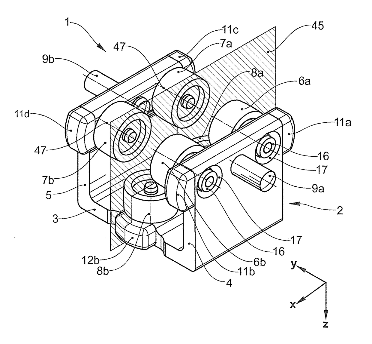
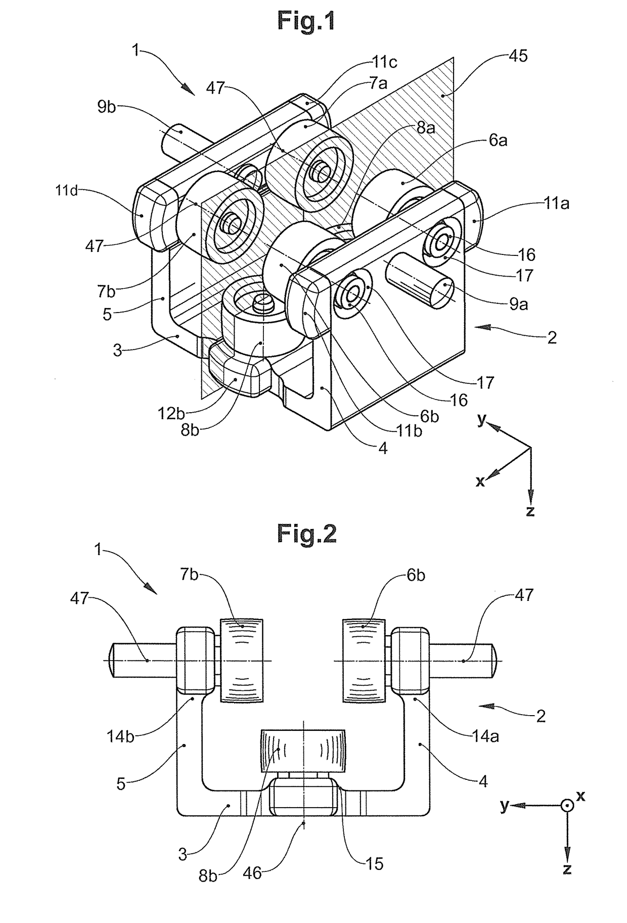
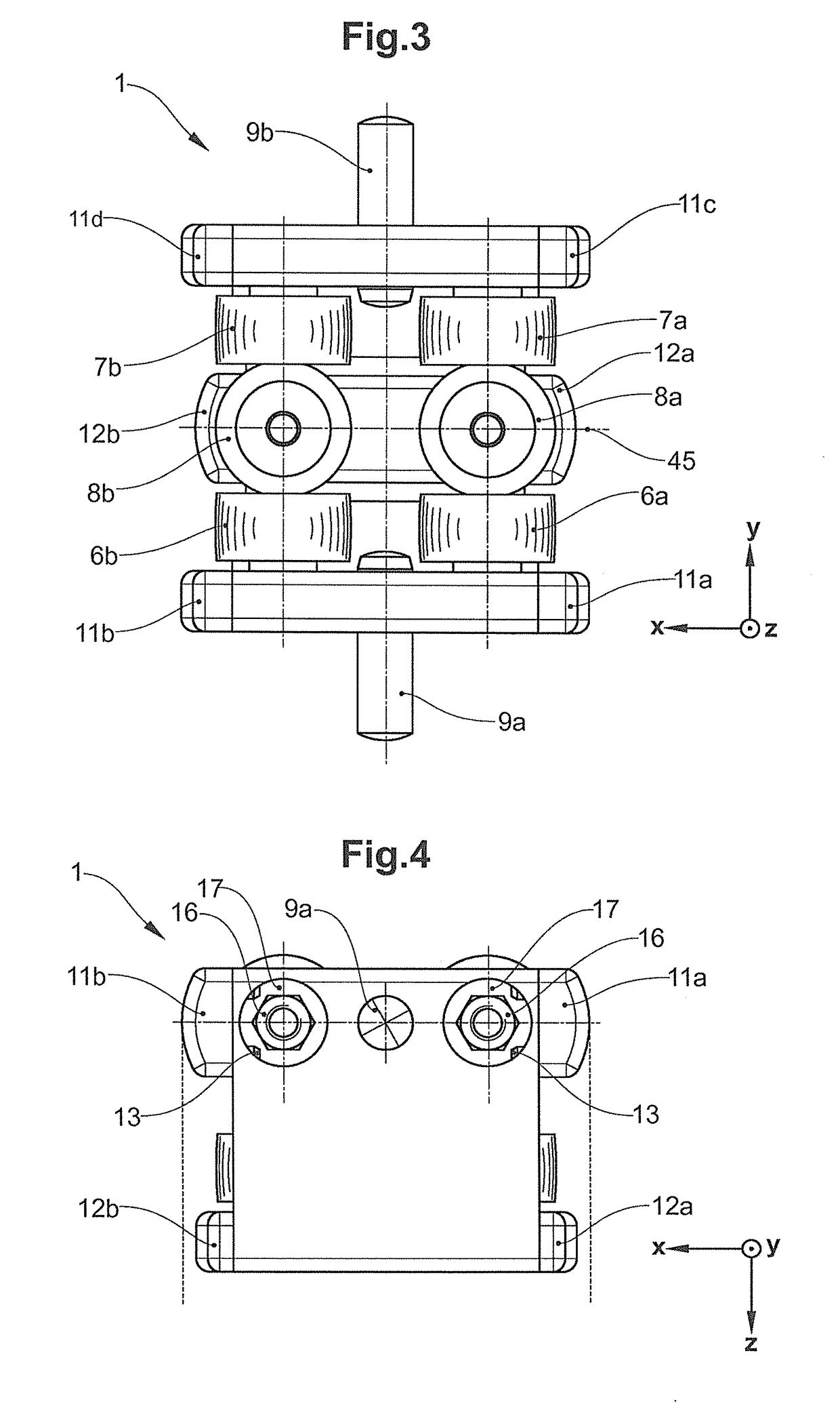
[0096]FIGS. 1 to 4 show various views of an embodiment of a carriage 1 for a conveyor, in particular a gravity-type conveyor. The carriage 1 shown comprises a carriage body 2 which in the cross section is U-shaped, which has (horizontal) connection portion 3 which in this embodiment is disposed below, and a first and a second (vertical) leg 4 and 5, respectively, which are laterally contiguous to said connection portion 3. On account thereof, the carriage shown is capable of embracing a running rail according to FIG. 5 and to run thereon as an external runner. In the embodiment shown, two first rollers 6a, b which act as support rollers are disposed on the internal side of the first leg 4. Two second rollers 7a, b which likewise act as support rollers are disposed on the internal side of the second leg 5. All first and second rollers each are mounted so as to be rotatable about a rotation axis 47 (FIG. 2).

[0097]As is shown in FIGS. 2 and 3, the rotation axes 47 of the first and of t...


PUM


Abstract

A carriage for a conveyor comprising a carriage body which is configured for embracing a running rail and which comprises a first and a second leg which are connected by a connection portion, wherein the first leg has first rollers which are attached to the internal side of the first leg, and the second leg has second rollers which are attached to the internal side of the second leg, and the connection portion has third rollers which are attached to the internal side of the connection portion, it is provided according to the invention that the first and the second rollers are vertically disposed, and the third rollers are horizontally disposed.

Description

BACKGROUND OF THE INVENTIONField of the Invention[0001]The present invention relates to the conveying of wares. Said present invention relates to a carriage for a conveyor, in particular for a gravity-type conveyor, to a conveyor system, in particular a gravity-type conveyor system, and to a method for operating a conveyor system, in particular a gravity-type conveyor system.Discussion of Related Art[0002]In the case of producing and post-processing of goods, as well as in the case of picking and packing orders, automated conveying of wares plays an important role. Gravity-type conveyors, in particular gravity-type suspended conveying systems herein are distinguished inter alia in that the former enable conveying of wares to be repositioned from the floor to otherwise non-utilized spaces within our without buildings. Suspended conveyor installations are therefore often fastened overhead on supports which are attached to the ceiling, to walls, or to individual pillars which are faste...

Claims


Application Information

Patent Timeline
Patent Type & Authority Applications(United States)
IPC IPC(8): B65G9/00B65G39/12B65G19/02B65G17/20
CPCB65G9/002B65G39/12B65G19/025B65G17/20
Inventor FENILE, ROBERTOKAELIN, ERICH
Owner FERAG AG
Why Eureka
Try Eureka