Two-step hot forming of steels

a technology of steel alloy and hot forming, which is applied in the direction of heat treatment equipment, manufacturing tools, furnaces, etc., can solve the problems of die cutting being typically uneffective, and achieve the effect of saving time, energy and cos

Inactive Publication Date: 2018-08-02
GM GLOBAL TECH OPERATIONS LLC
View PDF3 Cites 7 Cited by
  • Summary
  • Abstract
  • Description
  • Claims
  • Application Information

AI Technical Summary

Benefits of technology

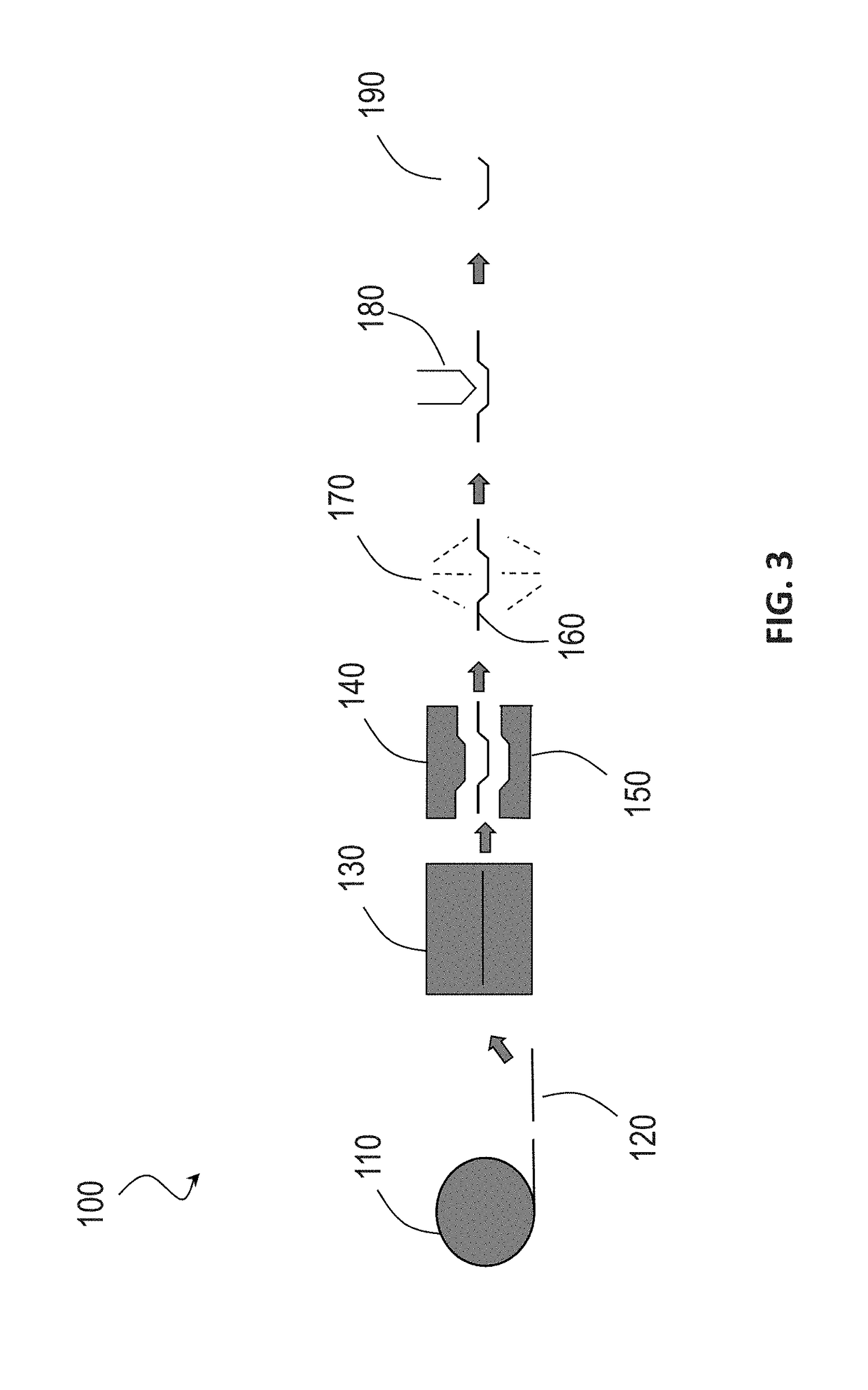
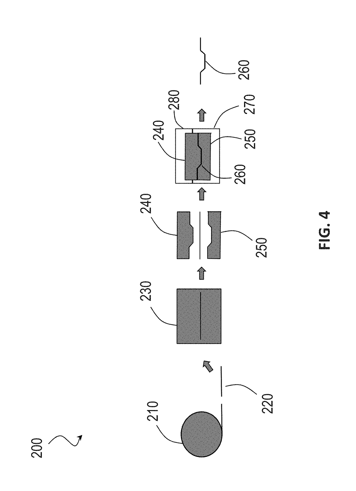
[0056]In another example, the process may consist essentially of the following steps. A blank comprised of a medium-Mn steel alloy is heated to a temperature of less than or equal to about 850° C. to austenitize the steel alloy. The blank is ten press hardened to form a press-hardened component. The press-hardened component is formed a second time at a temperature of greater than or equal to about the martensitic finish temperature. The further forming includes at least one of trimming, punching, or re-striking the press-hardened component. The press-hardened component is cooled at a controlled rate between the martensitic start temperature and the martensitic finish temperature such that the press-hardened component has a microstructure comprising martensite at greater than or equal to about 80% to less than or equal to about 98% and retained austenite at less than or equal to about 20% to greater than or equal to about 2%. In certain other variations, such a process may be further limited as further consisting essentially of, any combination of, or all of the following: (1) heating the blank to a temperature of less than or equal to about 800° C. to austenitize the medium-Mn steel alloy; (2) having a steel alloy comprised of carbon at greater than or equal to about 0.1 wt. % to less than or equal to about 0.4 wt. % and manganese at greater than or equal to about 5 wt. % to less than or equal to about 12 wt. %; (3) a PHS component having an ultimate tensile strength of greater than or equal to about 1,700 MPa; (5) air cooling the press-hardened component to the martensitic finish temperature after further forming the press-hardened component; and (6) galvanizing the medium-Mn steel alloy blank before heating. Notably, such a process excludes any laser cutting that are often required in conventional processes and quenching the press-hardened component, which can result in time, energy, and cost savi...

Problems solved by technology

After shot blasting, further forming of the PHS component is typically accomplished with las...

Method used


Image

  • Two-step hot forming of steels
  • Two-step hot forming of steels
  • Two-step hot forming of steels

Examples


Embodiment Construction

[0018]Example embodiments will now be described more fully with reference to the accompanying drawings.

[0019]Example embodiments are provided so that this disclosure will be thorough, and will fully convey the scope to those who are skilled in the art. Numerous specific details are set forth such as examples of specific compositions, components, devices, and methods, to provide a thorough understanding of embodiments of the present disclosure. It will be apparent to those skilled in the art that specific details need not be employed, that example embodiments may be embodied in many different forms and that neither should be construed to limit the scope of the disclosure. In some example embodiments, well-known processes, well-known device structures, and well-known technologies are not described in detail.

[0020]The terminology used herein is for the purpose of describing particular example embodiments only and is not intended to be limiting. As used herein, the singular forms “a,”“a...


PUM

PropertyMeasurementUnit
Temperatureaaaaaaaaaa
Fractionaaaaaaaaaa

Abstract

Methods for press hardening steel alloys comprised of medium-Mn are provided. The press-hardened steel alloy may have an ultimate tensile strength (UTS) of at least 1,700 MPa and a tensile elongation of at least 8%. The press-hardened steel alloy may be formed in two forming steps above the martensitic finish temperature. The press-hardened steel may have a microstructure comprising martensite at greater than or equal to about 80% to less than or equal to about 98% and retained austenite at less than or equal to about 20% to greater than or equal to about 2%.

Description

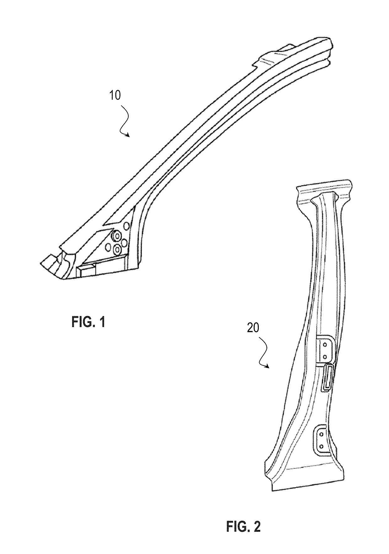
INTRODUCTION[0001]This section provides background information related to the present disclosure which is not necessarily prior art.[0002]The present disclosure relates to two-step forming methods of press-hardening steel alloys to form high-strength press-hardened components.[0003]Press-hardened steel (PHS), also referred to as “hot-stamped steel,” is one of the strongest steels used for automotive body structural applications, having tensile strength properties on the order of about 1,500 mega-Pascal (MPa) and total elongation on the order of about 5% to 6%. Such steel has many desirable properties and uses, including forming steel components with significant increases in strength-to-weight ratios. Further, PHS components have become increasingly prevalent in various industries and applications, including general manufacturing, construction equipment, automotive or other transportation industries, home or industrial structures, and the like. For example, in automotive manufacturin...

Claims


Application Information

Patent Timeline
IPC IPC(8): C21D9/00C23C2/06C23C2/40C23C2/28C22C38/04C21D8/00C21D1/18B21D22/02
CPCC21D9/0068C23C2/06C23C2/40B21D22/022C22C38/04C21D8/005C21D1/18C23C2/28C21D2211/008C21D2211/001C23C2/26B21D35/005C21D6/005B32B15/013
Inventor WANG, JIANFENGLU, QISACHDEV, ANIL K.
Owner GM GLOBAL TECH OPERATIONS LLC
Why Eureka
Try Eureka