Axial fan

a technology of axial fan and axial fan body, which is applied in the direction of mechanical equipment, non-positive displacement pumps, liquid fuel engines, etc., can solve the problems of inability to reduce the thickness of the axial impeller, the distance between the bottom wall and the front wall of the electric motor facing the bottom wall of the hub is limited as much as possible, and the axial dimensions of the impeller cannot be reduced

Active Publication Date: 2018-08-02
SPAL AUTOMOTIVE
View PDF3 Cites 1 Cited by
  • Summary
  • Abstract
  • Description
  • Claims
  • Application Information

AI Technical Summary

Benefits of technology

[0034]The aim of this invention is to provide an axial electric fan which is free of the problem of noise introduced by the resonance frequencies.

Problems solved by technology

Moreover, during the design stage the distance between the bottom wall of the hub and the front wall of the electric motor facing the bottom wall of the hub is limited as much as possible.
However, since the axial dimensions of the impeller (its thickness) cannot be reduced below a certain structural limit, especially for high outputs wherein the impellers have very large diameters, in order to attempt to limit as much as possible the axial dimensions of the electric fan it is necessary to reduce as much as possible the distance between the bottom wall of the hub and the surface of the motor facing the bottom wall of the hub itself.
In addition to drawbacks mentioned above relative to the axial dimensions, which will be discussed further below, the electric fan unit and, more specifically, the rotor and impeller, have vibration problems.
It is known that the impellers of axial fans driven by electric motors (of any type: brushless, DC etc.) generally have a problem of transmission by the motor to the impeller of a torque ripple having a frequency which is generally a multiple of the number of revolutions of the motor, which is superposed on the desired continuous torque.
In conclusion the so-called torque ripple induces vibration phenomena amplified at the resonance frequency of the impeller unit, shaft, motor rotor which in turn generate unwanted and unacceptable acoustic noise effects.
With reference to the above description regarding the need to reduce the axial dimensions of the electric fan unit, one must conclude that the use of the latter for cooling heat exchangers in the automotive sector results in a series of limitations which means that the use of the traditional damping structures described above is not practical to resolve the above-mentioned noise problem.
As mentioned above, the market request for minimum axial length of the electric fan unit provides only a few millimetres of motor shaft to couple the impeller to the motor and in particular the reduced distance between the bottom wall of the hub and the wall of the motor facing the bottom wall of the hub does not allow the use of traditional rubber dampers.
Moreover, the specifications due to environmental requirements and the reliability / life of the product are very stringent.
Also for these reasons, rubber is absolutely unsuitable for being used to make damping devices or structures.

Method used


Image

  • Axial fan
  • Axial fan
  • Axial fan

Examples


Embodiment Construction

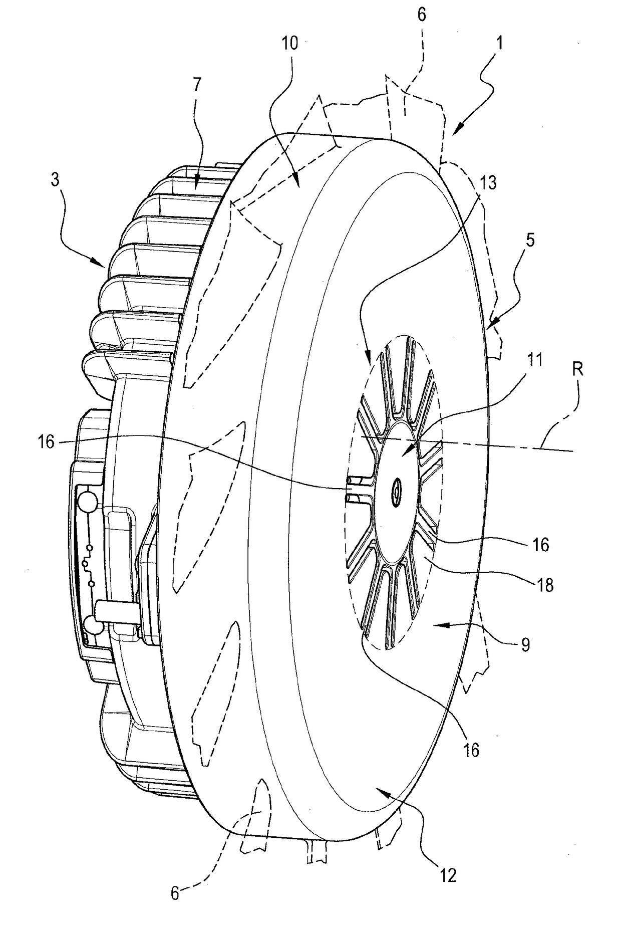
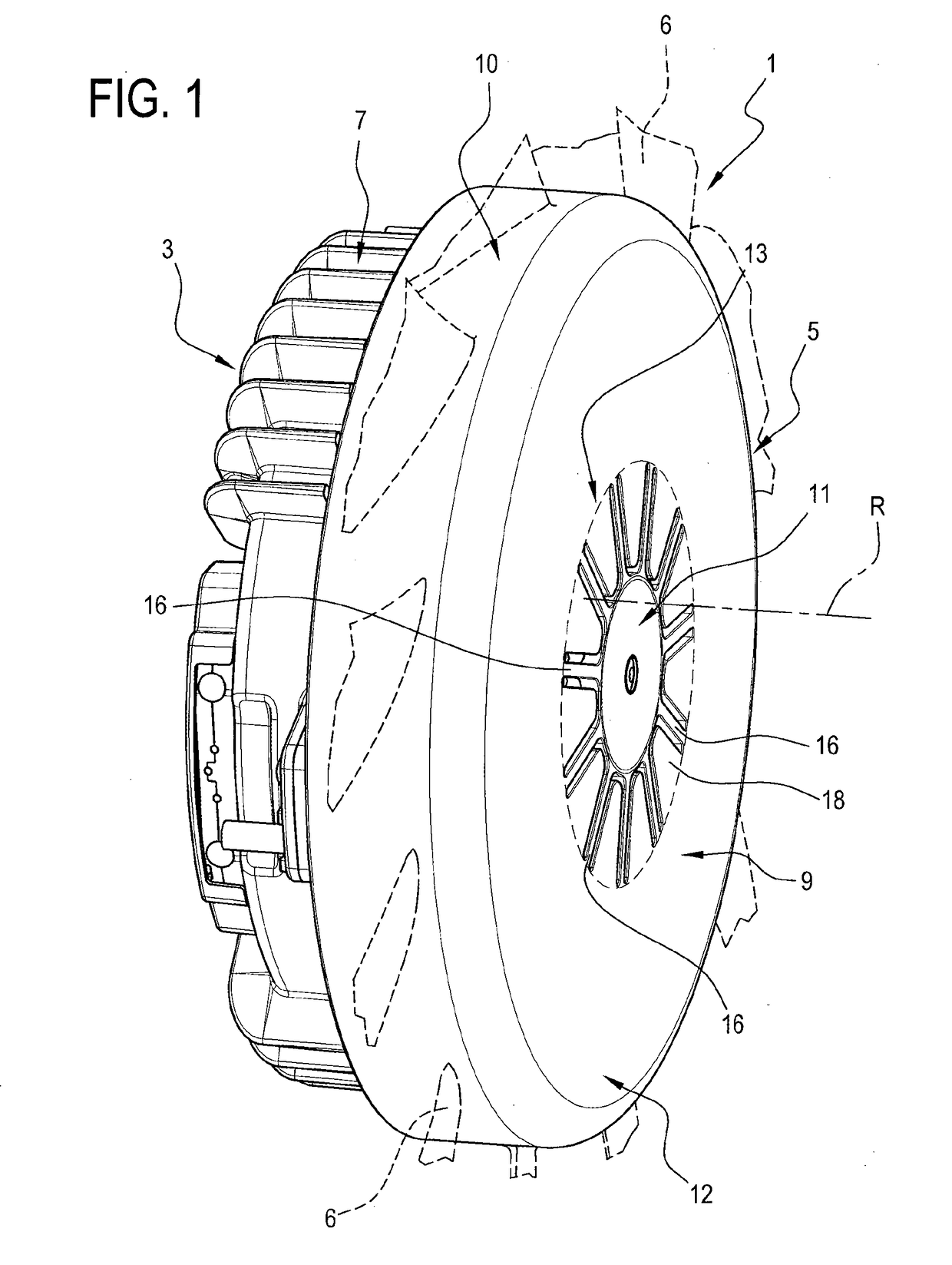
[0047]With reference to the accompanying drawings and in particular to FIGS. 1 and 2, the numeral 1 denotes in its entirety a fan unit according to this invention.

[0048]The fan unit 1 is preferably destined for automotive applications in the cooling of radiators.

[0049]The fan unit 1 comprises an axial fan 2 with an axis of rotation R, an electric motor 3 and an axial flow impeller 4 driven and rotated by the motor 3 about the axis R.

[0050]As illustrated in FIGS. 3 and 4, the fan 4 is equipped with a hub 5 and a plurality of blades 6 which extend from the hub 5.

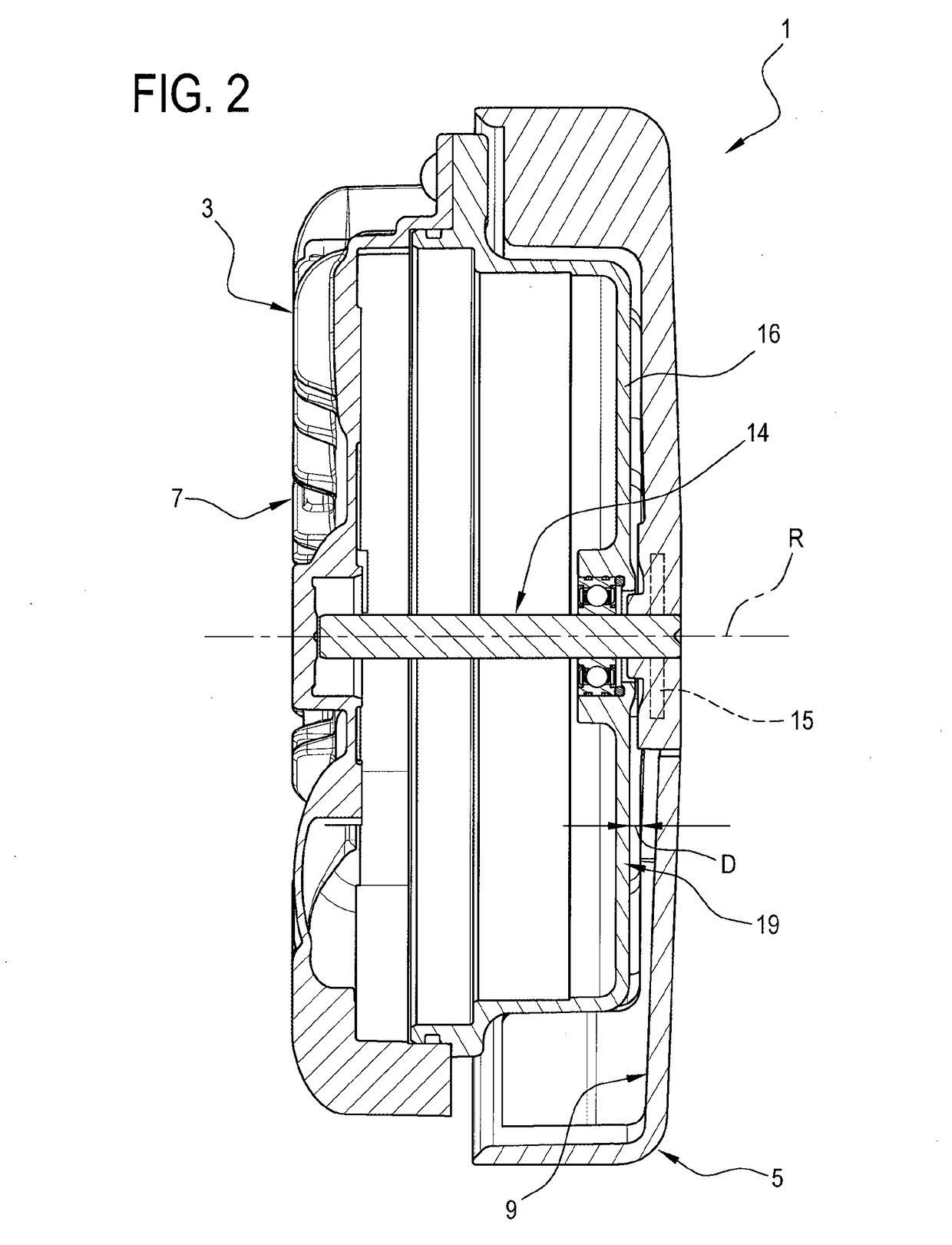
[0051]As illustrated in particular in FIGS. 1 and 2, the motor 3, preferably of the closed and sealed type, substantially of known type and described only insofar as is necessary to understand the invention, comprises an external casing 7 and a shaft 8, coaxial with the axis R, to which the impeller 4 is connected.

[0052]The impeller 4 or, rather, the axial fan 2 comprises the above-mentioned hub 5 which is in turn shaped in th...


PUM


Abstract

An axial fan includes a motor, an impeller and a hub of the impeller for connecting to a shaft of the motor. A bottom wall of the hub has a central portion, and an outer annular portion connected to the central portion by an intermediate portion defined by a plurality of blades arranged radially and angularly distributed about an axis of rotation. The blades are elasto-plastic blades and are able to prevent the impeller from moving axially parallel to the axis, moving radially perpendicular to the and a bending of the impeller with movements normal to the plane in which the mean surface of the impeller itself lies. The blades allow a movement with torsional bending around the axis to allow the damping of the resonance frequencies of the assembly formed by the impeller-shaft-rotor.

Description

TECHNICAL FIELD[0001]This invention relates to an axial fan and, in particular, to an axial electric fan for automotive applications.[0002]The prior art fans, to which reference is made in this specification, comprise an axial fan and an electric motor which drives the fan and are usually referred to as “axial electric fans”.BACKGROUND ART[0003]The electric motor has a substantially cylindrical casing, a stator unit and a rotor unit, housed inside the casing and coupling means designed to couple the rotor unit to the impeller so as to rotate it.[0004]The above-mentioned coupling means are normally defined by a shaft protruding from the casing, rotated by the rotor unit.[0005]In this description, for sake of simplicity, reference will always be made to the fact that the above-mentioned coupling means comprises a shaft protruding from the casing of the electric motor and rotated with the rotor unit, but without limiting the scope of the invention.[0006]The impeller has a connecting hu...

Claims


Application Information

Patent Timeline
Patent Type & Authority Applications(United States)
IPC IPC(8): F01D5/16F04D29/32F04D29/66
CPCF01D5/16F04D29/329F04D29/668F05D2300/501F05D2240/30F04D19/002
Inventor DEFILIPPIS, PIETRO
Owner SPAL AUTOMOTIVE
Why Eureka
Try Eureka