
A Combined Motion Capture System

a motion capture and combined technology, applied in the direction of television systems, speed/acceleration measurement, instruments, etc., can solve the problems of high cost of systems, inability to adapt to capture movements of other parts of the body, complex calibration process, etc., and achieve the effect of reducing cos

Inactive Publication Date: 2018-08-02
BEIJING NOITOM TECH
View PDF4 Cites 7 Cited by
  • Summary
  • Abstract
  • Description
  • Claims
  • Application Information

AI Technical Summary

Benefits of technology

The invention is a combined motion capture system that allows for different motion captures using the same set of motion capture devices, reducing cost. The system includes inertial sensor units that can be mounted on various motion capture objects in different ways, making it easy to achieve different motion capture objectives. The invention also includes a terminal processor that calibrates the motion based on the combination mode and the motion capture object, correcting any installation errors of the inertial sensor unit. Overall, the invention provides a flexible and cost-effective solution for motion capture.

Problems solved by technology

But this system is expensive, its calibration process is very complex, and it can only capture the motions in the overlapping areas of the cameras.
Furthermore, when the object's movement is complicated, the marks may easily block or be confused with each other, resulting in erroneous results.
It cannot be adapted to capture movements of other parts of the body (such as lower body) by changing the mounting positions of the inertial sensors.
Thus, if a user wants to change the measured part, he / she has to purchase additional motion capture systems or advanced systems with more inertial sensors, which will increase the cost.

Method used


Image

  • A Combined Motion Capture System
  • A Combined Motion Capture System
  • A Combined Motion Capture System

Examples


Embodiment Construction

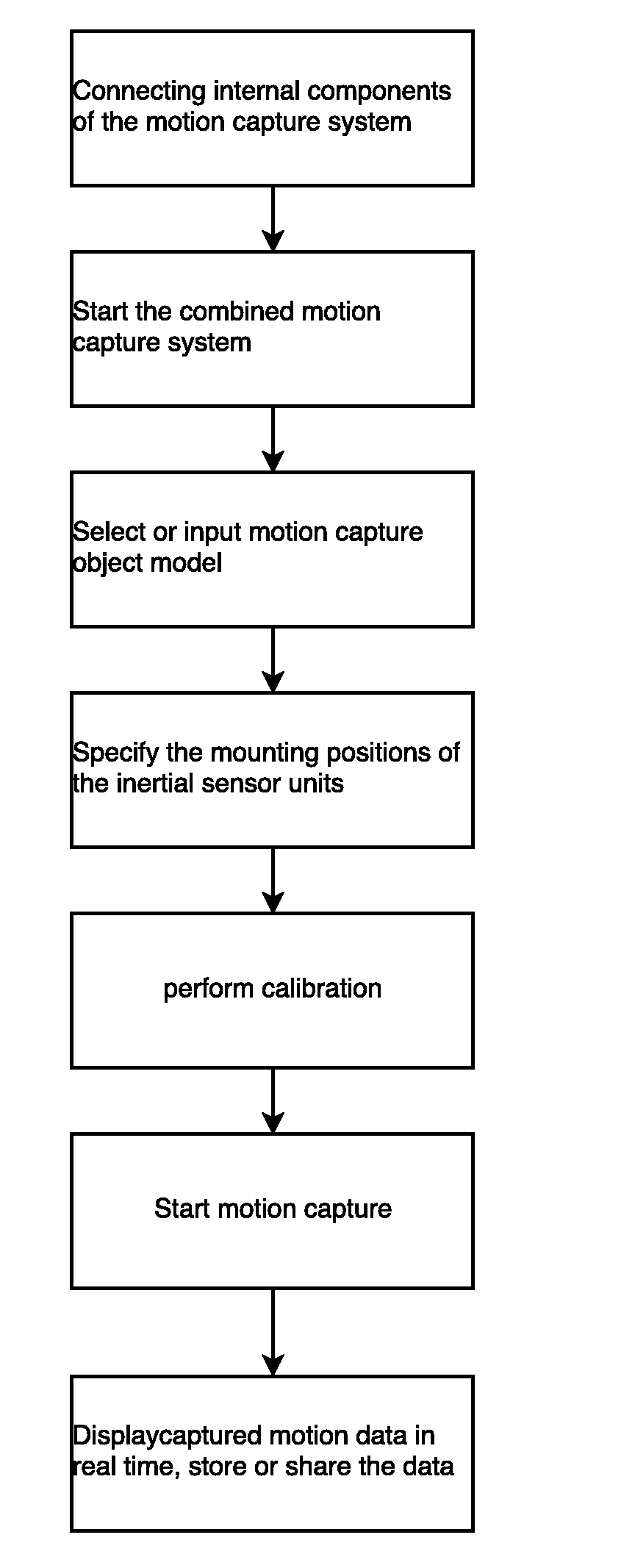
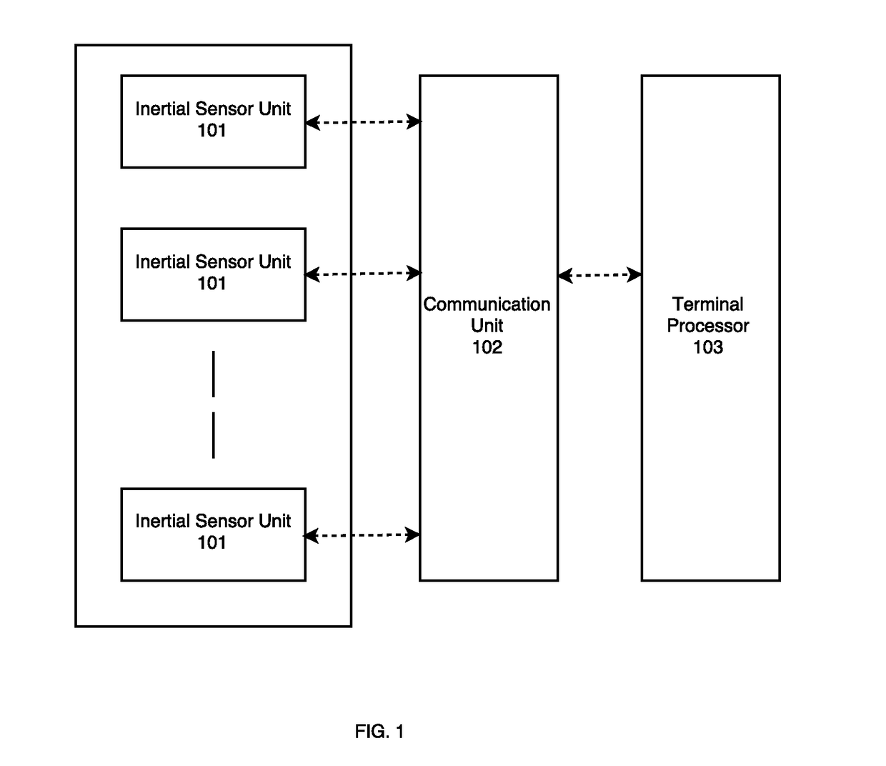
[0075]This implementation of the combined motion capture system comprises thirty inertial sensor units, three RF communication units, and one terminal processor. The inertial sensor units communicate with the RF communication unit via wired serial communication connection, and the RF communication unit communicates with the terminal processor via Wi-Fi connection. The multi-object combined motion capture implementation may be used in a plurality of application cases. It can form three sets of independent ten-sensor based upper body motion capture systems, each set of system comprising an RF communication unit and ten inertial sensor units, and the three sets of upper body motion capture systems may connect to the same terminal processor, achieving multi-person motion capture. The combination of the present invention may also be in the form of a set of full body (with fingers of both hands) system with a tool for implementing the complete capture of a single person's full body motion...


PUM


Abstract

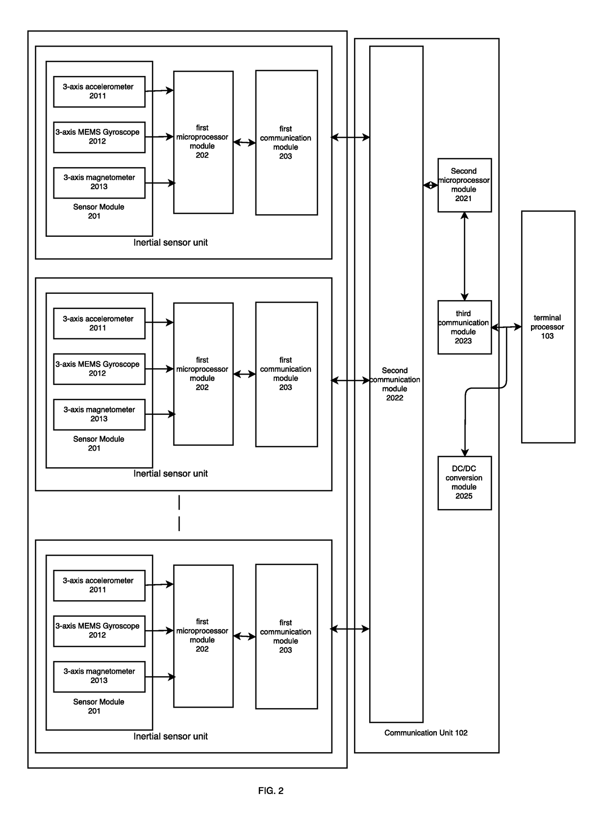
A combined motion capturing system comprises multiple inertial sensor units (101), at least one communication unit (102), and a terminal processor (103). The inertial sensor units (101) are connected to the communication unit (102). The communication unit (102) is connected to the terminal processor (103). The inertial sensor units (101) are mounted at positions of one or more motion capture objects according to different combination modes, and measure motion information of the positions where the inertial sensor units (101) are mounted, and send the motion information to the communication unit (102). The communication unit (102) receives the motion information output by inertial sensors, and sends the motion information to the terminal processor (103). The terminal processor (103) acquires information about the motion capture objects and mounting position information of the inertial sensor units (101), generates combination modes of the inertial sensor units (101) according to the information of the motion capture objects and the mounting position information, receives the motion information sent by the communication unit (102), and processes the received motion information according to the combination modes to acquire complete postures and the motion information of the motion capture objects. By freely combining the same set of motion capturing devices, different motion capturing objectives are achieved, and the cost is reduced.

Description

TECHNICAL FIELD[0001]The invention relates to motion capture technology, in particular to a combined motion capture system.BACKGROUND TECHNOLOGY[0002]Motion capture technology can digitally record movements of an object. Currently, the commonly used motion capture technologies include optical-based motion capture and inertial-sensor-based motion capture, each being described below:[0003]An optical-based motion capture system usually consists of four to thirty-two cameras, which are arranged around the object to be measured (hereinafter, the “motion capture object”). The key parts of the motion capture object are tagged with special light reflection points or light emitting points as marks for visual recognition and processing. After system calibration, the cameras continuously capture the movements of the object and store the series of captured images for analysis and processing, calculating the spatial location of each mark at any moment so that its accurate trajectory may be deter...

Claims


Application Information

Patent Timeline
Patent Type & Authority Applications(United States)
IPC IPC(8): G01C25/00G06F3/01B81B7/02B81B7/04
CPCB81B7/04B81B2201/0235B81B2201/0242G01C25/005G06F3/011B81B7/02G06F3/0346G01C21/10
Inventor DAI, RUOLILIU, HAOYANGLI, LONGWEICHEN, JINZHOUGUI, BAOJIA
Owner BEIJING NOITOM TECH
Learn More