Hybrid Encoder System for Position Determination

a position determination and encoder technology, applied in the direction of electrical/magnetically converting sensor output, measuring devices, instruments, etc., can solve the problems of changing the sensitivity of the sensor and therefore the measurement accuracy, no longer generating output signals with measureable amplitudes, and no longer sense sensors, etc., to achieve high resolution position determination, reduce hardware, and reduce the effect of coils

Active Publication Date: 2018-08-02
ROCKWELL AUTOMATION TECH
View PDF0 Cites 12 Cited by
  • Summary
  • Abstract
  • Description
  • Claims
  • Application Information

AI Technical Summary

Benefits of technology

[0015]The present inventors have further determined that the aforementioned curvilinear encoder system can be improved to provide absolute mechanical position determination and high resolution position determination with fewer coils and reduced hardware by configuring the teeth of the mover to have a curvilinear profile with first and second harmonics while providing coils on only teeth of the stator. The curvilinear shape of the teeth of the mover can allow a single excitation coil on the stator to produce a pick-up signal with different harmonics in pick-up coil on the stator instead of requiring multiple excitation coils to produce multiple pick-up signals multiple in pick-up coils to convey the same information.
[0016]In one aspect, the present invention provides an integrated hybrid-pole reluctance resolver with absolute mechanical position detection, high resolution and mechanical position identification with reduced system cost. The present invention provides an independent cart system with position feedback, temperature stability and air gap insensitivity. The cart can be configured for travel along linear and / or curved sections of modular track systems.

Problems solved by technology

Conversely, when the cart is away from the group of magnetic sensors on the track, the magnetic sensors no longer sense the position magnet of the cart and, in turn, no longer generate output signals having measureable amplitudes.
In addition, such magnetic sensors are typically sensitive to temperature variations that change sensor sensitivity and therefore measurement accuracy.

Method used


Image

  • Hybrid Encoder System for Position Determination
  • Hybrid Encoder System for Position Determination
  • Hybrid Encoder System for Position Determination

Examples


Embodiment Construction

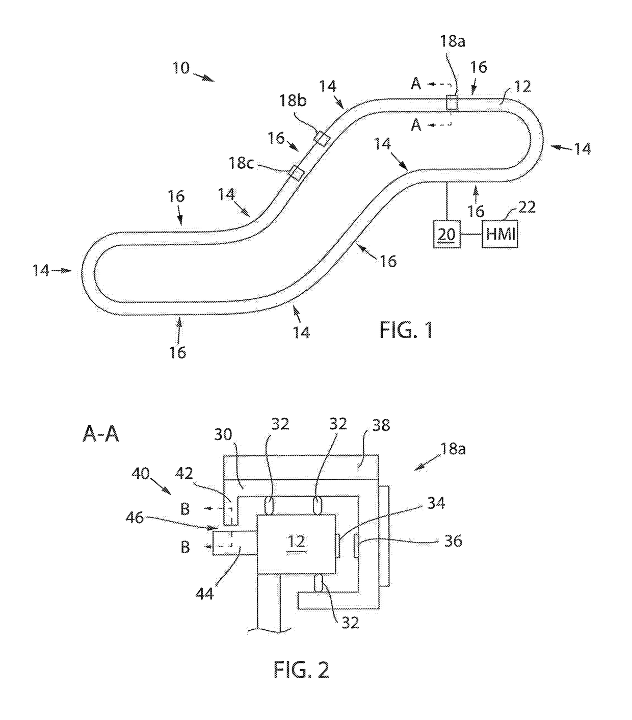
[0038]Referring now to FIG. 1, in accordance with an aspect of the invention, an exemplar industrial control system 10 includes a track 12 having curved sections 14 and linear sections 16. Multiple carts 18, such as carts 18a, 18b and 18c, can be provided for moving objects along the track 12 from one location to another for accomplishing various tasks in the industrial control system 10. The track 12 can be connected to a controller 20, which can include a processor executing a program stored in a non-transient medium, and which can communicate with a Human Machine Interface (“HMI”) 22 for providing I / O, for carrying out various aspects of the invention as will be described herein. It will be appreciated that the track 12, being flexibly capable of curved and linear sections according to various geometries, can be configured to implement a wide variety of paths and orientations as may be required in the environment.

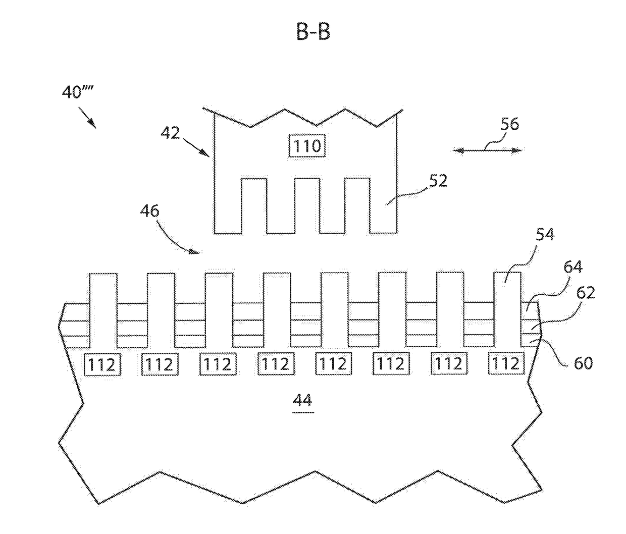
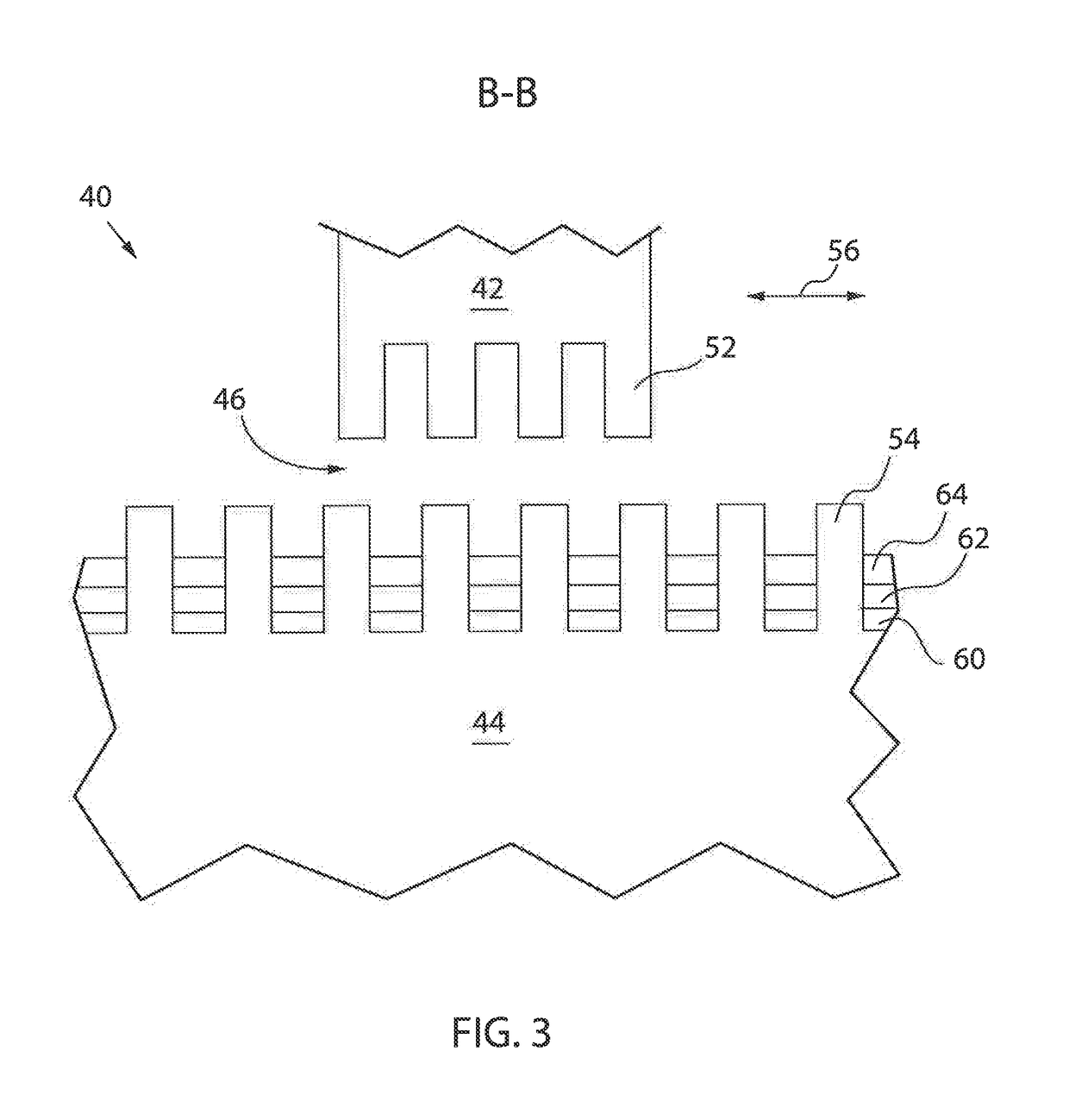
[0039]With additional reference to FIG. 2, a cross sectional view o...


PUM


Abstract

A linear and curvilinear encoder is provided in which absolute mechanical position and high resolution position determination can be obtained using a cart having a mover with “hybrid” teeth, configured in a curvilinear profile or shape, moving along a curvilinear track with a stator having teeth. The absolute mechanical position and high resolution position determination can be detected on the track by applying an excitation signal to a coil surrounding particular teeth of the stator to produce an electromagnetic (EM) field which can be influenced by the profile or shape of the teeth of the mover. A resulting pick-up signal can then be detected in a pick-up coil surrounding particular teeth of the stator with different harmonics in the pick-up signal corresponding to harmonics of the profile or shape of the teeth.

Description

CROSS-REFERENCE TO RELATED APPLICATION(S)[0001]This application is a continuation in part of U.S. patent application Ser. No. 15 / 420,548, filed on Jan. 31, 2017, entitled “Curvilinear Encoder System for Position Determination,” the entirety of which is incorporated herein by reference,FIELD OF THE INVENTION[0002]The subject matter disclosed herein relates generally to industrial control systems, and more particularly, to a linear and curvilinear encoder system for determining a position of a cart for moving objects along a track.BACKGROUND OF THE INVENTION[0003]In industrial control systems, it is often desirable to move objects from one location to another for accomplishing various tasks. For example, rolling conveyors are often used to move objects from one location to another for interacting with different machines of an industrial control process, such as a first machine at a first location for placing a box, a second machine at a second location for filling the box, and a third...

Claims


Application Information

Patent Timeline
Patent Type & Authority Applications(United States)
IPC IPC(8): G01D5/20
CPCG01D5/2046G01D5/145G01D5/2073G01D2205/77G01D2205/771
Inventor SUN, XIKAISMIT, PETER M.COOPER, MARK R.HAYA, OLIVER C.DA SILVA, ADERIANO M.
Owner ROCKWELL AUTOMATION TECH
Why Eureka
Try Eureka