
Echo measuring apparatus, echo sounding apparatus, multibeam echo measuring apparatus, multibeam echo sounding apparatus and aperture synthetic sonar

a multi-beam echo and measuring device technology, applied in the field of echo measuring devices, multi-be multi-beam echo measuring devices, etc., can solve the problems of difficult detection and correction of ship motion due to wave influence, inability to reduce the horizontal direction of sounding, and long time required for sounding, so as to save electric power consumption of the apparatus, improve the s/n ratio, and raise the horizontal direction

Active Publication Date: 2018-08-02
AQUAFUSION LTD
View PDF7 Cites 5 Cited by
  • Summary
  • Abstract
  • Description
  • Claims
  • Application Information

AI Technical Summary

Benefits of technology

The invention improves the resolution in the horizontal direction by shortening the transmitting period and increasing the S / N ratio. This allows for accurate detection of ship motion and correction without using an acceleration sensor, reducing costs and errors. Additionally, the correlation between front and rear receiving echo signals improves the detection of ship motion. Overall, the invention improves the accuracy and efficiency of the apparatus.

Problems solved by technology

Such a point that the transmitting period cannot be shortened results in that a resolution in the horizontal direction of the sounding cannot be decreased.
Therefore, the conventional echo sounding apparatus has such a problem that in the case of raising the resolution in the horizontal direction of the sounding, a time required for the sounding becomes long.
As mentioned above, in the conventional echo sounder, the transmitting period cannot be shortened and since the transmitting period is longer or almost equal to a period of the ship motion due to the waves, it is difficult that the ship motion due to an influence by the waves is detected and corrected.

Method used


Image

  • Echo measuring apparatus, echo sounding apparatus, multibeam echo measuring apparatus, multibeam echo sounding apparatus and aperture synthetic sonar
  • Echo measuring apparatus, echo sounding apparatus, multibeam echo measuring apparatus, multibeam echo sounding apparatus and aperture synthetic sonar
  • Echo measuring apparatus, echo sounding apparatus, multibeam echo measuring apparatus, multibeam echo sounding apparatus and aperture synthetic sonar

Examples


first embodiment

1. First Embodiment

[0136]FIG. 7 shows an electrical construction of the first embodiment of the invention. A transmission trigger pulse generator 1 for generating a transmission trigger pulse of a pulse signal of a predetermined period is provided. The transmission trigger pulse is supplied to a gold code generator 2 as a PN sequence generator and a display or recording apparatus 10. The display and / or recording apparatus 10 includes: a display apparatus such as a liquid crystal or the like and / or a recording apparatus such as a semiconductor memory or the like; and an arithmetic operating apparatus for displaying or recording.

[0137]The gold code generator 2 generates a gold code synchronously with the transmission trigger pulse. A PN (Pseudo random Noise) sequence such as an M sequence or the like other than the gold code may be used. The gold code is supplied to a pulse modulator 3. The gold code is digital-modulated by, for example, a BPSK (Binary Phase Shift Keying). A frequency...

second embodiment

3. Second Embodiment

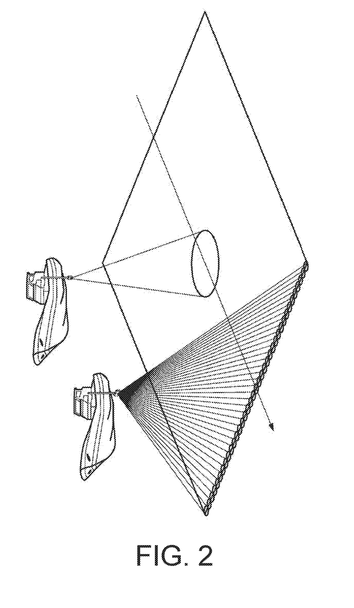
[0170]A multibeam echo sounder will be described as a second embodiment of the invention. As shown in FIG. 29, the multibeam echo sounder has a directivity called a fan beam which is narrow in the progressing direction of a ship and is wide in the right / left direction, and a transmission signal is transmitted from one transmitter. Since such an apparatus has a plurality of beams which are wide in the front / rear direction of the ship and are narrow in the right / left direction so as to cross the transmission beam, it is called a multibeam echo sounder. FIG. 30 shows a construction of a multibeam echo sounder of the second embodiment.

[0171]In a manner similar to that mentioned above, as a construction of the transmitting side, the transmission trigger pulse generator 1, gold code generator 2, pulse modulator 3, transmitting amplifier 4, and transmitter 5 are provided. An underwater ultrasonic wave is transmitted from the transmitter 5. The transmission signal is a s...

third embodiment

4. Third Embodiment

[0174]The third embodiment of a ship motion correcting apparatus according to the invention will be described. As described with reference to FIGS. 5 and 6, in the case of measuring the sea bottom (which denotes the sea bottom surface) by an ultrasonic wave, a depth which is measured becomes deeper or shallower than the true sea bottom because the reference sea level is subjected to a ship motion of the waves. FIG. 31 shows submarine measurement values which are obtained by measuring the actual sea bottom in the case of assuming that a period of the ship motion of a ship by the waves is equal to 1 Hz and an upper / lower motion is equal to ±1 m. The measurement value of the sea bottom by the echo sounder changes by an influence of the ship motion. When the ship is lifted up by the waves, the measurement value is detected as a value deeper than the actual depth of the sea bottom (shown by a broken line). When the ship is lifted down, it is detected as a value shallow...


PUM


Abstract

An echo measuring apparatus has: a transmission signal forming unit for forming a transmission signal by a pseudo noise sequence signal; a transmitting unit for transmitting the transmission signal as an ultrasonic wave into the water; a receiving unit for receiving an echo of the ultrasonic wave; and a correlator for discriminating the echo corresponding to the transmission signal by executing a correlating process to the echo by the pseudo noise sequence signal and measuring a distance to a measurement target on the basis of a time difference between the transmission signal and the echo, wherein assuming that a velocity of a sound wave in the water is equal to Vu and the distance to the measurement target is equal to D, a period of the transmission signal includes a case where it is equal to or less than (2D / Vu).

Description

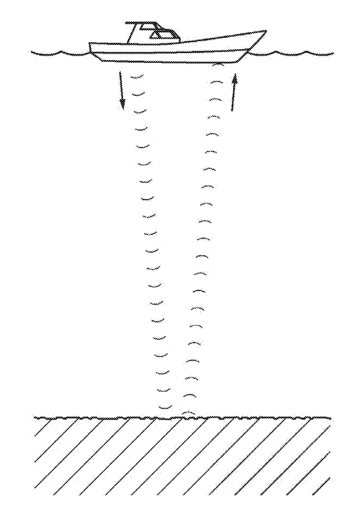
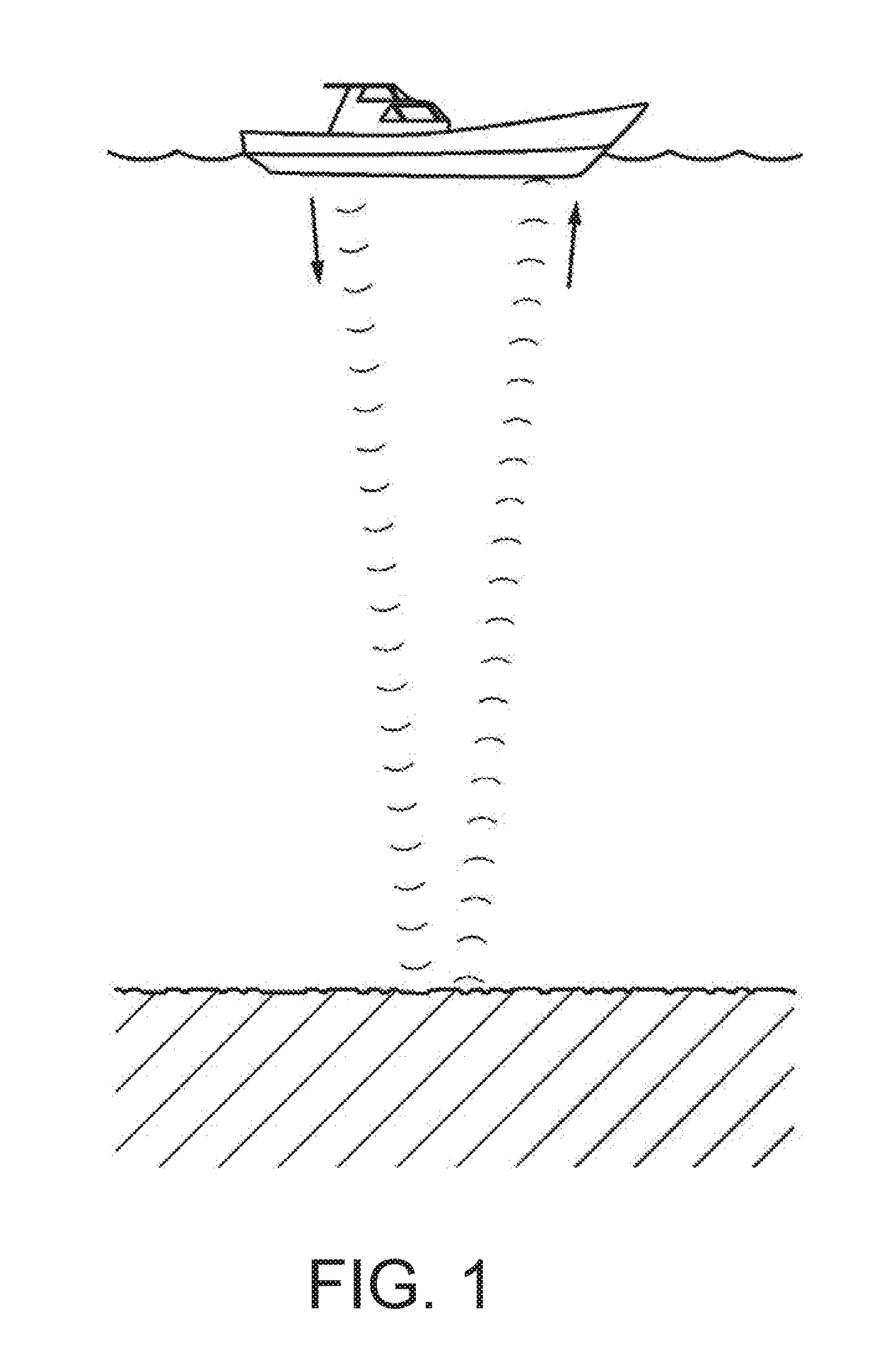
TECHNICAL FIELD[0001]The present invention relates to an echo measuring apparatus, an echo measuring method, a ship motion component detecting apparatus, a ship motion component detecting method, a multibeam echo measuring apparatus, and an aperture synthetic sonar for measuring a distance, for example, a depth by using an ultrasonic wave which propagates in the water.BACKGROUND ART[0002]An echo sounding technique in the ocean has been used for long. As shown in FIG. 1, an ultrasonic pulse is generated from an ultrasonic transducer, an echo obtained when its sound wave is reflected from a target (sea bottom) is captured, and its depth is measured by using a propagation speed (about 1500 m / sec) of the sound wave in the water. An echo sounding apparatus using such a principle has been realized as a product 50 or more years ago. Even nowadays, a depth of sea bottom is measured by using such a principle. Such a technique called “echo location” has continuously been used without being ch...

Claims


Application Information

Patent Timeline
Patent Type & Authority Applications(United States)
IPC IPC(8): G01S7/52G01S15/10G01S15/89
CPCG01S7/52003G01S15/104G01S15/89G01S7/527G01S15/8904
Inventor SASAKURA, TOYOKIMATSUO, IKUO
Owner AQUAFUSION LTD
Learn More