
Projection optical apparatus and projector

a technology of projection optical apparatus and projector, which is applied in the direction of instruments, television systems, picture reproducers using projection devices, etc., can solve the problems of undesirable impact and undesirable damage of projectors, and achieve satisfactory exterior appearance of the projector and small weight

Active Publication Date: 2018-08-02
SEIKO EPSON CORP
View PDF2 Cites 4 Cited by
  • Summary
  • Abstract
  • Description
  • Claims
  • Application Information

AI Technical Summary

Benefits of technology

The invention described in this patent text relates to a configuration for a projector that can be attached to an image forming apparatus. The technical effects of this configuration include reducing impact on the projection optical apparatus in cases of impact and suppressing vibration caused by impact. The configuration allows for easy attachment and detachment of different projection optical apparatuses while maintaining a good appearance.

Problems solved by technology

Impact could undesirably be applied to a projector, for example, by rough handling of the projector when it is installed on a desktop or any other surface.
In a projector including a projection optical apparatus that is heavier than the projection lens described in JP-A-2012-226033 and a projector including a projection lens having a center of gravity located in a position further separate from the flange section, significant breakage could undesirably occur due to an increase in load acting on the projector.

Method used


Image

  • Projection optical apparatus and projector
  • Projection optical apparatus and projector
  • Projection optical apparatus and projector

Examples


Embodiment Construction

[0041]An embodiment of the invention will be described below with reference to the drawings. In the following drawings, each component is so drawn at a scale or a ratio different from an actual value as to be large enough to be recognizable in the drawings.

[0042]A projector according to the present embodiment will be described below.

[0043]The projector according to the present embodiment modulates light emitted from a light source in accordance with image information and enlarges and projects the modulated light on a screen or any other projection surface.

Primary Configuration of Projector

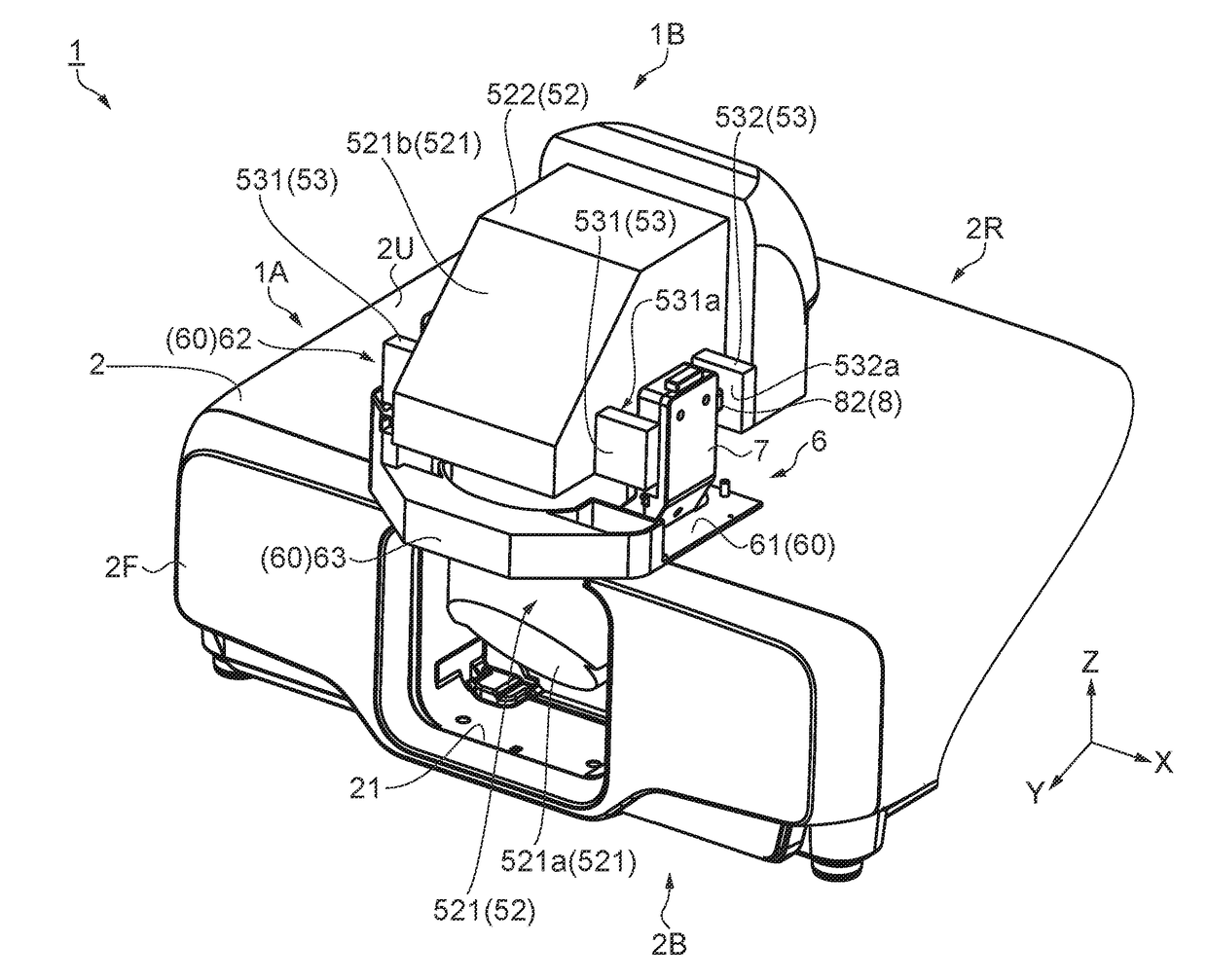
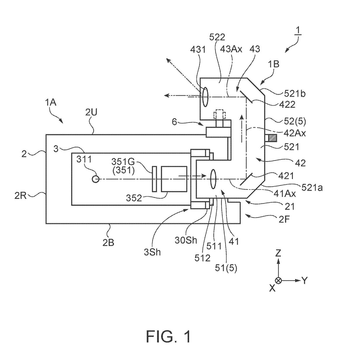
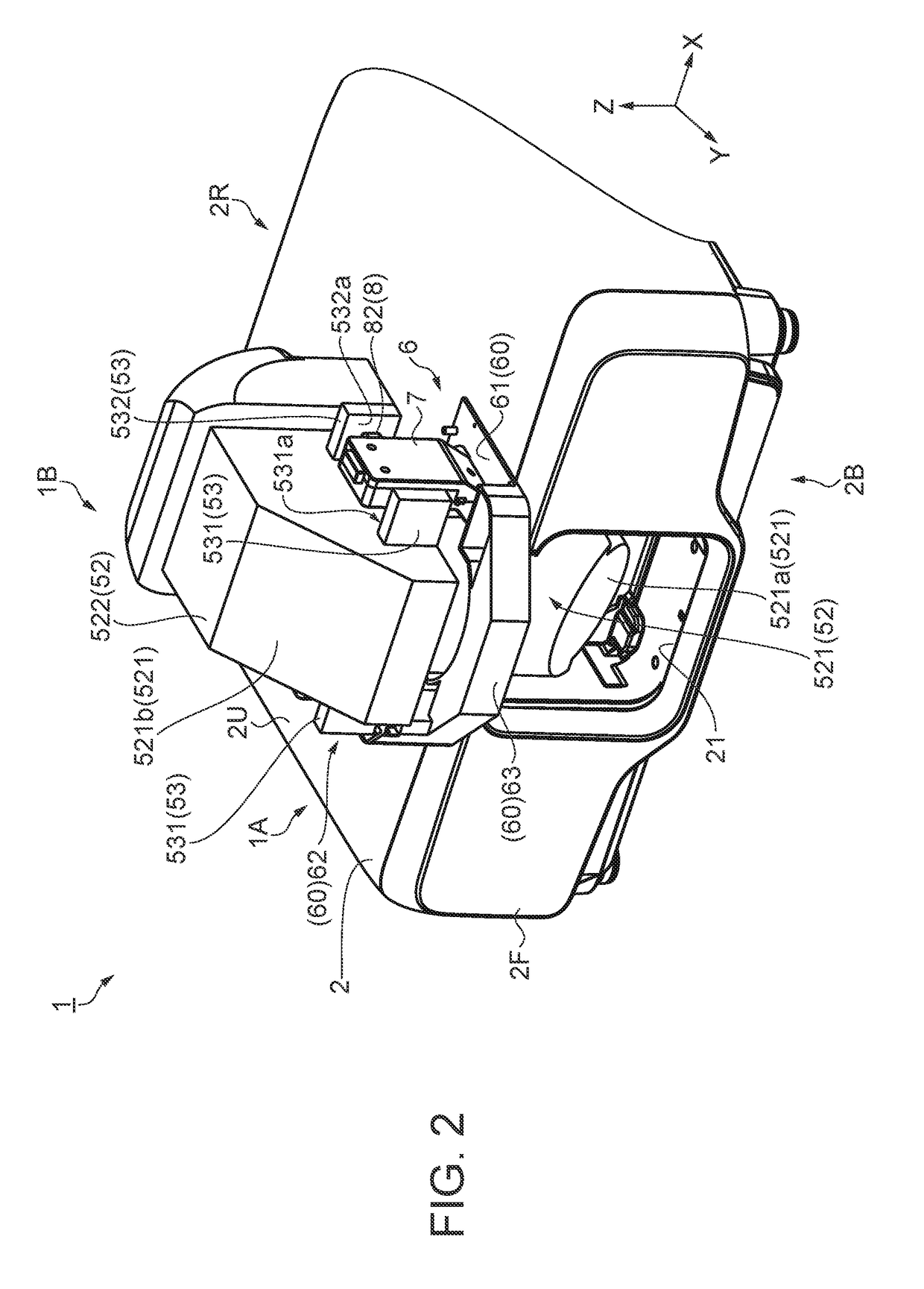
[0044]FIG. 1 is a side view diagrammatically showing a primary configuration of a projector 1 according to the present embodiment. FIG. 2 is a perspective view showing the exterior appearance of the projector 1.

[0045]The projector 1 includes an image forming apparatus 1A, a projection optical apparatus 1B, which is so supported by the image forming apparatus 1A that the projection optical apparatus...


PUM

PropertyMeasurementUnit
gravityaaaaaaaaaa
torqueaaaaaaaaaa
pressing forceaaaaaaaaaa

Abstract

A projection optical apparatus includes an optical system and a projection optic enclosure that accommodates the optical system. The optical system includes a first optical system on which the image light is incident, and the projection optic enclosure includes a first accommodation section that accommodates the first optical system and includes a flange section (supported section) supported by the image forming apparatus and a first wall section and a second wall section that face each other in a first direction (Y direction) that intersects the direction along a line that connects the flange section to the center of gravity of the projection optical apparatus.

Description

BACKGROUND1. Technical Field[0001]The present invention relates to a projection optical apparatus and a projector.2. Related Art[0002]There has been a known projector including a light modulator that modulates light emitted from a light source in accordance with image information and a projection optical apparatus that projects the light modulated by the light modulator on a projection surface. Further, there has been a proposed projector that incorporates a projection optical apparatus including a short-throw lens and other components for allowing projection from a position close to the projection surface (see JP-A-2012-226033, for example) and a proposed projector that incorporates a projection optical apparatus that changes the direction of light outputted from a light modulator and projects the light.[0003]The projector described in JP-A-2012-226033 includes an optical unit including a projection optical apparatus (projection lens) and a holder, an exterior enclosure, and other ...

Claims


Application Information

Patent Timeline
Patent Type & Authority Applications(United States)
IPC IPC(8): G03B17/54G02F1/13G03B21/28H04N5/64H04N9/31
CPCG03B17/54G02F1/13G03B21/28H04N5/64H04N9/3141G03B21/14G03B21/145
Inventor KUROTA, IPPEITSUCHITANI, HIROSHI
Owner SEIKO EPSON CORP
Learn More