
Belt conveyance apparatus

Inactive Publication Date: 2018-08-02
CANON KK
View PDF7 Cites 0 Cited by
  • Summary
  • Abstract
  • Description
  • Claims
  • Application Information

AI Technical Summary

Benefits of technology

The patent is for a device that moves goods using a belt. The device helps to guide the belt and reduces stress on the edges of the belt, which can help to make it stronger and last longer.

Problems solved by technology

However, if the entire circumference of the sliding portion is formed in a tapered shape, a low material proof strength (yield stress) of the belt member causes a distortion at an edge portion of the belt member winding around the sliding portion when the belt member runs on the sliding portion.
This distortion possibly shortens the life of the belt member.
If the belt member is thin, the belt member is likely to wave to easily produce a shearing stress at the edge portion of the belt member, possibly causing a crack.
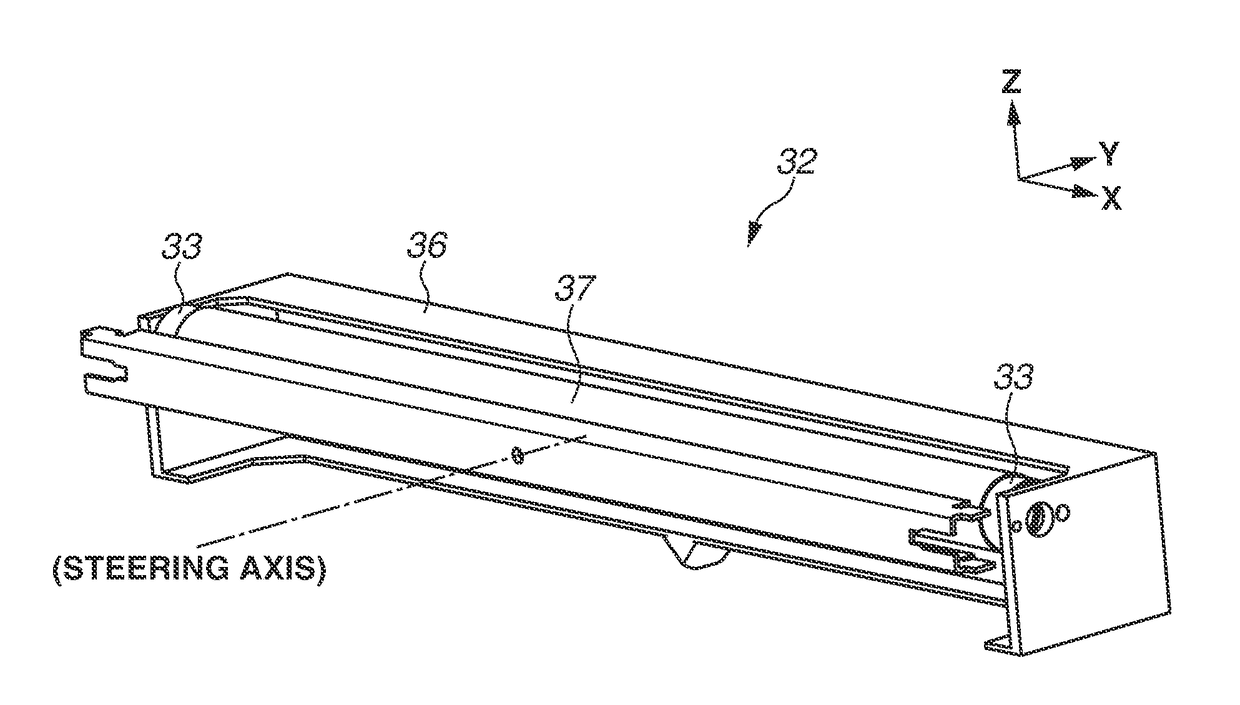
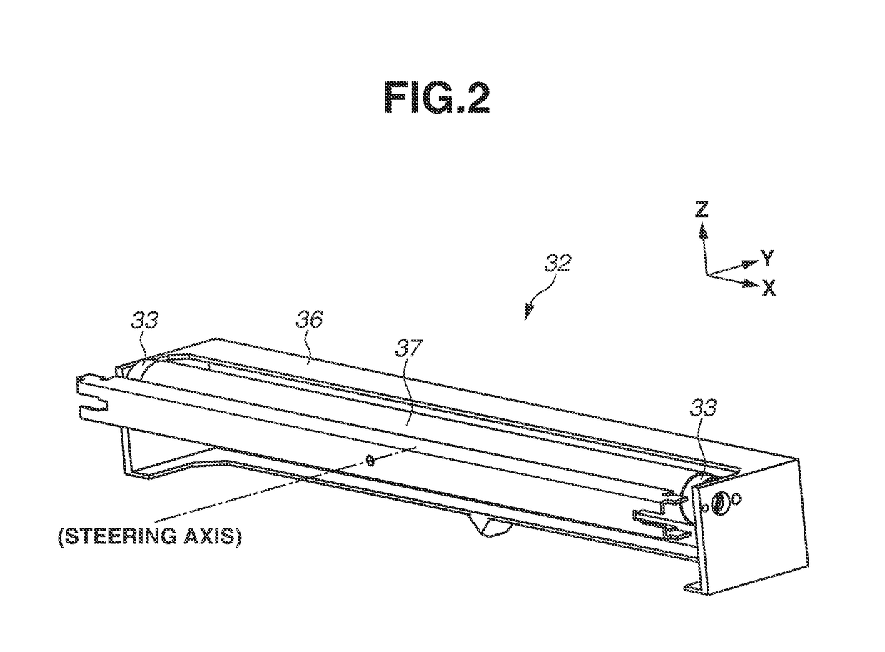
As a result, it becomes hard to ensure the rudder angle of the steering roller for controlling the lateral movement of the belt member, possibly making it hard to ensure sufficient steering performance.

Method used


Image

  • Belt conveyance apparatus
  • Belt conveyance apparatus
  • Belt conveyance apparatus

Examples


examples

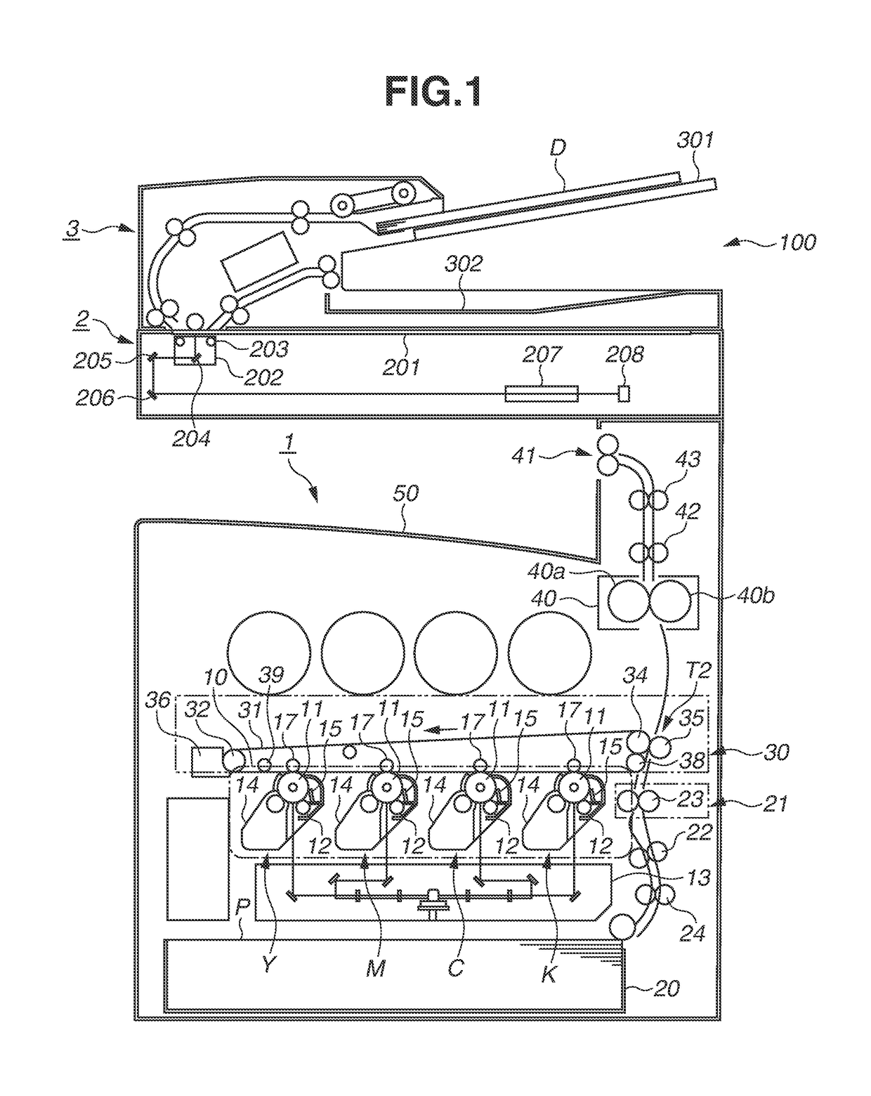
[0094]A simulation performed to confirm the effects of the present exemplary embodiment will be described below. A simulation for calculating the steering performance according to an example satisfying the conditions of the present exemplary embodiment and the steering performance according to the comparative example illustrated in FIGS. 3A and 3B will be described below.

[0095]According to the example, 5.6 mm (L2=175.8 mm) was set as the sliding width w2 of the intermediate transfer belt 31 on the sliding ring 33 on the side in the direction of the belt lateral movement during rotation of the intermediate transfer belt 31. The tilting rudder angle of the steering roller 32 in this case was calculated through the simulation. FIG. 9A illustrates the result of the calculation.

[0096]In the simulation, the taper angle at the ±90-degree positions of the sliding ring 33B on the Z′ axis line perpendicularly intersecting with the Y′ axis line illustrated in FIG. 7B was varied as illustrated ...


PUM

PropertyMeasurementUnit
Lengthaaaaaaaaaa
Fractionaaaaaaaaaa
Fractionaaaaaaaaaa

Abstract

A stretching roller for stretching an intermediate transfer belt is tiltably disposed, and includes a sliding ring unrotatably disposed at both axial ends of a roller portion. The intermediate transfer belt winds and slidably rotates around the sliding ring. The sliding ring has a tapered portion inclined so that the outer diameter increases toward the axial end side of the stretching roller. The tapered portion is formed so that the inclination angle with respect to the central axis of the stretching roller differs at least in part in the circumferential direction.

Description

BACKGROUND OF THE INVENTIONField of the Invention[0001]The present disclosure generally relates to a belt conveyance apparatus having a rotary belt member stretched by a plurality of tension rollers.Description of the Related Art[0002]For example, an image forming apparatus is known to be configured to transfer toner images from a plurality of photosensitive drums to an intermediate transfer belt as an endless belt member in an overlapped way, and collectively transfer the images from the intermediate transfer belt to a recording material. Such an intermediate transfer belt is stretched and rotatably driven by a plurality of tension rollers. In this rotating state, the intermediate transfer belt laterally moves to either side because of the outer diameter accuracy of the rollers and the alignment accuracy between the rollers.[0003]Japanese Unexamined Patent Application Publication No. 2001-520611 discusses a configuration in which a sliding portion having a tapered outer circumferen...

Claims


Application Information

Patent Timeline
IPC IPC(8): G03G15/16G03G15/00B65G39/16
CPCG03G15/1615G03G15/755G03G15/161B65G39/16G03G2215/00156G03G15/162G03G15/2053G03G2215/2016B65H29/16B65H5/021B65H2301/44334B65H2404/252
Inventor FUMOTO, MASATAKAKANAI, DAIKUDO, RAN
Owner CANON KK
Features
  • Generate Ideas
  • Intellectual Property
  • Life Sciences
  • Materials
  • Tech Scout
  • Unparalleled Data Quality
  • Higher Quality Content
  • 60% Fewer Hallucinations
Learn More