
Compressor Blade Locking Mechanism in Disk with Axial Groove

a technology of compression blade and locking mechanism, which is applied in the direction of mechanical equipment, machines/engines, liquid fuel engines, etc., can solve the problems of increasing the number of required parts, complex manufacturing process, and device that does not effectively relieve the stress of axial for

Active Publication Date: 2018-08-09
DOOSAN HEAVY IND & CONSTR CO LTD
View PDF8 Cites 1 Cited by
  • Summary
  • Abstract
  • Description
  • Claims
  • Application Information

AI Technical Summary

Benefits of technology

The invention relates to a device for locking compressor blades in place. The device includes a first locking plate located on the attachment of the compressor blade and a second locking plate located on the disk where the attachment is engaged. The design of the device ensures that the first and second locking plates are aligned with each other, allowing for secure attachment of the blade to the disk. This design prevents movement or misalignment of the blades during operation, leading to improved performance and reliability of the gas turbine.

Problems solved by technology

However, while axial force of the compressor blade is very large, the above locking devices do not effectively relieve a stress of the axial force and require a complicated structure.
In addition, these techniques increase the number of required parts and make the manufacturing process complicated.

Method used


Image

  • Compressor Blade Locking Mechanism in Disk with Axial Groove
  • Compressor Blade Locking Mechanism in Disk with Axial Groove
  • Compressor Blade Locking Mechanism in Disk with Axial Groove

Examples


first embodiment

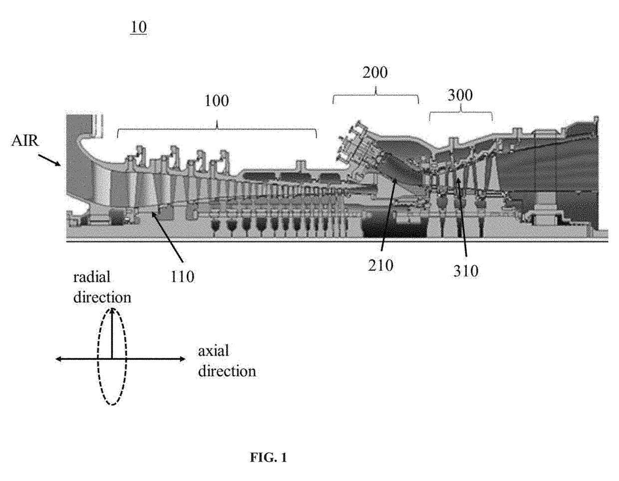
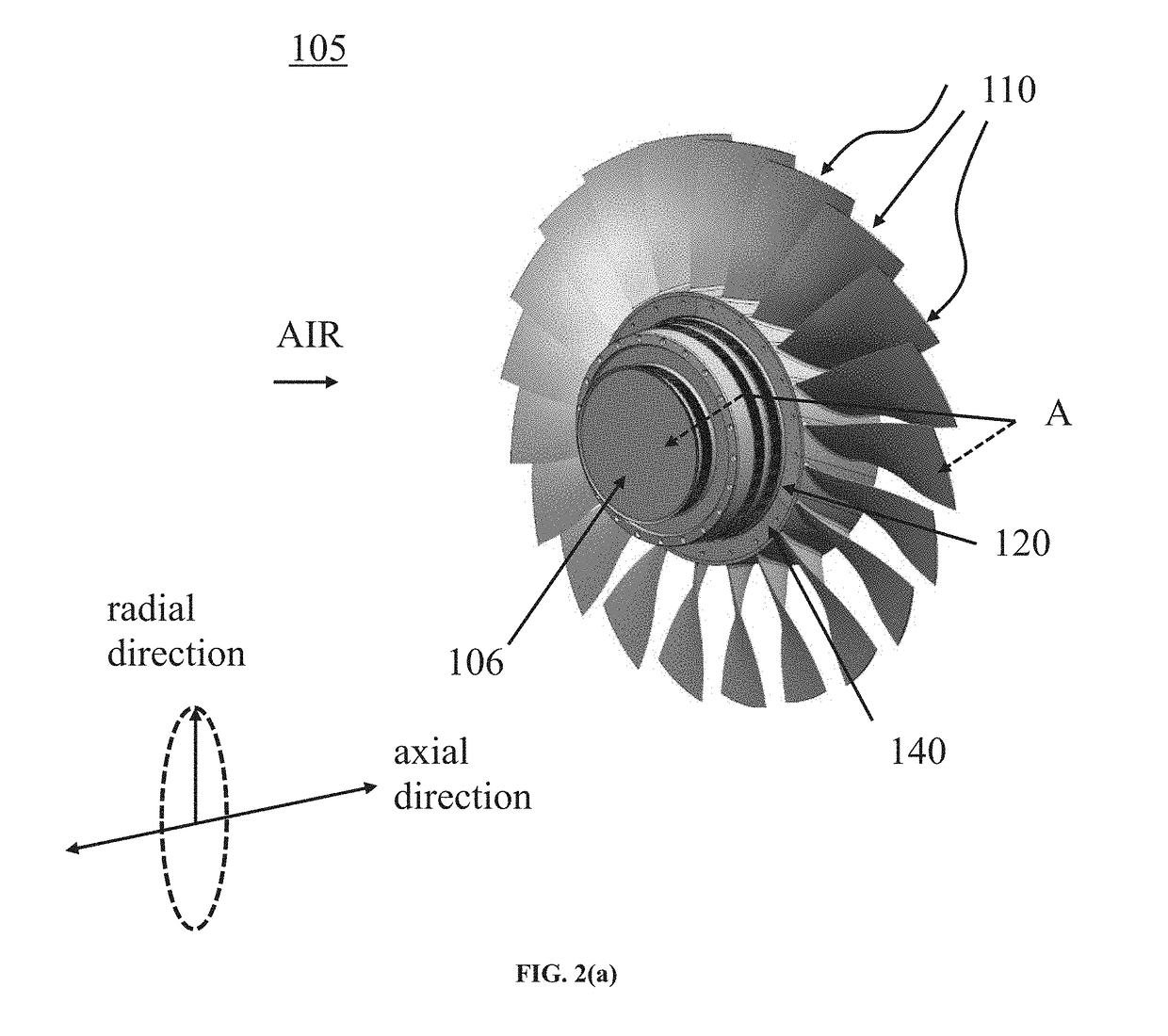
[0024]FIGS. 2(a) and 2(b) are front and rear perspective views, respectively, of a compressor bladed disk according to the subject invention. A compressor bladed disk 105 can be used in any stage in the compressor 100 and the compressor bladed disk 105 can be coupled with another compressor bladed disk 105. For example, FIGS. 2(a) and 2(b) show the compressor bladed disk 105 used in the first stage of the compressor 100.

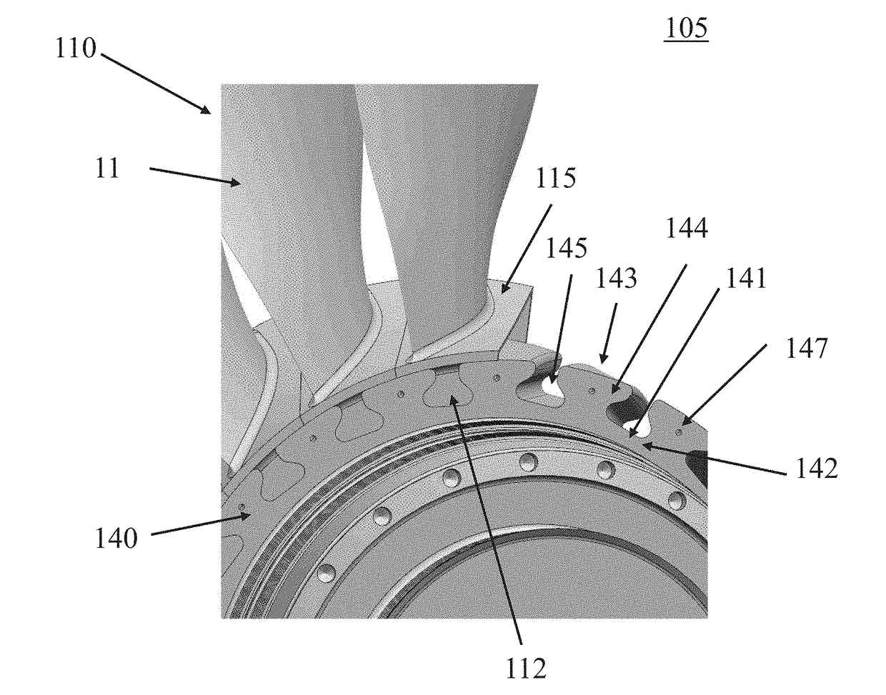
[0025]The compressor bladed disk 105 includes a disk 140 having a rim shape, a compressor blade 110 engaged with the disk 140, a first locking plate 120 disposed on the disk 140 and the compressor blade 110 at an upstream side of the compressor blade 110, and a second locking plate 130 disposed on the disk 140 and the compressor blade 110 at a downstream side of the compressor blade 110, wherein the air flows from the upstream side to the downstream side. In addition, the compressor bladed disk 105 of the first stage is connected to the front shaft 106 at the upstrea...

second embodiment

[0038]FIG. 9 is a perspective view of a compressor bladed disk according to the subject invention. The first locking plate 120 further includes a first shield portion 129 extended in the axial direction, thereby covering the front surface 121 and the first locking plate hole 127.

[0039]FIG. 10 is a cross-sectional perspective view of a compressor blade locking device according to a second embodiment of the subject invention. FIG. 11 is a cross-sectional view of a compressor bladed disk according to a second embodiment of the subject invention. Referring to FIGS. 10 and 11, the first shield portion 129 is extended from the first annular plate 128 in the axial direction and the first shield portion 129 is protruded in the axial direction against the upstream platform 114. As a result, the first shield portion 129 inhibits some parts from being introduced into the compressor blade 110 at the upstream side. For example, in case a bolt 126 coupled with the first locking plate hole 127 is ...

embodiment 1

[0042] A compressor blade locking device, comprising:

[0043]an attachment configured to be engaged in a groove of a disk;

[0044]a first locking plate disposed on an upstream surface and an upstream fillet of the attachment; and

[0045]a second locking plate disposed on a downstream surface of the attachment.

[0046]Embodiment 2. The compressor blade locking device according to embodiment 1, wherein the groove of the disk is an axial groove.

[0047]Embodiment 3. The compressor blade locking device according to embodiment 1, further comprising an upper platform disposed on the attachment, an upstream platform disposed on the upper platform over the upstream surface, and a downstream platform disposed on the upper platform over the downstream surface.

[0048]Embodiment 4. The compressor blade locking device according to embodiment 3, wherein the upstream platform and the upstream surface are connected to each other through the upstream fillet.


PUM


Abstract

A compressor bladed disk comprises a disk including an axial groove and a disk protrusion, a compressor blade including an attachment engaged with the axial groove of the disk, and a first locking plate disposed on the disk and the attachment, wherein the attachment includes an upstream surface and an upstream fillet connected to the upstream surface, wherein the upstream surface of the attachment and a protrusion front surface of the disk protrusion are aligned with each other, wherein a back surface of the first locking plate is disposed on the upstream surface of the attachment and the protrusion front surface of the disk protrusion, and wherein the first locking plate is disposed on the upstream fillet. The compressor bladed disk further comprises a second locking plate disposed on a downstream surface of the attachment.

Description

BACKGROUND[0001]The present invention relates to a compressor for a gas turbine, more particularly, to a compressor blade locking device for a compressor blade engaged in an axial groove of a disk. A gas turbine generally comprises a compressor, a combustor, and a turbine, wherein the compressor provides compressed air generated by a compressor blade to the combustor. During operation of the compressor, while the compressor blade is radially retained by a dovetail joint structure of an attachment of the compressor blade and an axial groove of a disk of the compressor, axial retention of the compressor blade requires an additional locking device because the axial groove of the disk has open ends in an axial direction. As the additional locking device, a longitudinal wedge is inserted between the attachment of the compressor blade and the axial groove of the disk or a plate is provided in front of the attachment of the compressor blade. However, while axial force of the compressor bla...

Claims


Application Information

Patent Timeline
Patent Type & Authority Applications(United States)
IPC IPC(8): F04D29/32F02C3/04F04D19/02F01D5/12
CPCF04D29/322F02C3/04F04D19/02F04D29/324F05D2240/35F05D2220/32F05D2240/30F05D2260/30F01D5/12F01D5/3015F01D5/323F04D29/644
Inventor MONTGOMERY, MATTHEWGOROSHCHAK, IURIIKWAK, JOOHWAN
Owner DOOSAN HEAVY IND & CONSTR CO LTD
Features
  • Generate Ideas
  • Intellectual Property
  • Life Sciences
  • Materials
  • Tech Scout
  • Unparalleled Data Quality
  • Higher Quality Content
  • 60% Fewer Hallucinations
Learn More