Fire door control system and method

a control system and door technology, applied in the field of fire door control system, to achieve the effect of preventing rotational movement, not easy to be mounted on the rotor, and easy reset by the user

Active Publication Date: 2007-11-27
OVERHEAD DOOR
View PDF15 Cites 32 Cited by
  • Summary
  • Abstract
  • Description
  • Claims
  • Application Information

AI Technical Summary

Benefits of technology

[0011]One advantage of the present invention is that the system may include a manual alarm switch. This manual alarm switch enables a user to manually test the system to assure that the system is functioning properly and is ready for an unexpected alarm condition. Furthermore, the system can be easily reset by the user. To reset the system, the user simply opens the door to its fully opened position. When the door reaches its fully opened position, a reset switch is actuated and sends a signal to the controller. The controller resets the system by changing the state of the system from any alarm mode that was present previously to a regular operational mode.
[0012]While various aspects of fire door systems of the present invention have been described generally above, the clutch of such a system has particular features that advantageously provide for lowering of the door under conditions of loss of primary power and in the case where the hand crank remains engaged during an alarm condition. The clutch may be connected to the secondary power source so that even if power is lost, the door can be shut in a controlled manner with the aid of the clutch. The clutch may have a rotor fixedly supported on the gear which in the present invention may be a sprocket. Thus, the rotor and the sprocket may be fixed together and may be adapted to be rotatively supported on the axle of the rollable door. The clutch may also have an armature including at least one spring supporting a flex plate. The armature also may have a mounting structure that fixedly supports the spring and flex plate on the axle. There may be a small gap between a face of the rotor and a face of the flex plate. The clutch may also have a coil that is supported within the rotor. The coil induces a magnetic field that attracts the flex plate to the rotor against the bias of the spring. Thus, the flex plate can be magnetically and frictionally engaged with the rotor to prevent rotational movement between the flex plate and the rotor. In this engaged condition, the spring substantially rigidly supports the flex plate on the support structure. Therefore, when the clutch is in the engaged condition, the sprocket is substantially rigid with the fire door axle and can hold or drive the axle.
[0013]For retrofit applications and for new installations, the clutch can be part of a larger fire door movement control assembly. The fire door movement control assembly may also include a mounting plate that is adapted for mounting the control assembly on support structure for a fire door. The mounting plate may have a through opening sized and positioned to receive the fire door axle therethrough. The mounting plate may also have a mounting platform that supports the controller, which can be an electronic controller, and other electrical components of the fire door movement assembly. This configuration of the clutch, mounting plate, controller, and other electrical components is very advantageous in retrofitting to existing fire doors as an upgrade to those systems. In particular, it is to be understood that any existing drive mechanism including, for example, a motor, a gear box, etceteras, can be used in conjunction with the present invention as long as the drive mechanism is adequate for the weight of the fire door and the wiring is proper and modifiable. Thus, virtually any existing fire door can be upgraded and provided with the advantages of the present invention by retrofitting the present invention to the existing fire door. It is to be noted that since the rotor rotates, the coil cannot easily be mounted on the rotor. Therefore, the fire door movement control assembly may also include coil fastening elements in the form of standoffs that support the coil on the mounting plate.
[0014]The present invention also relates to a method of controlling a fire door system. Generally, a method of controlling a fire door system may include controlling the fire door by an electronic controller during alarm conditions and non-alarm conditions. Accordingly, the fire door may be controlled by a motor during alarm conditions when a primary power source is on. The fire door may be controlled by a clutch during alarm conditions when the primary power source is off or when the system does not include a motor. In any case, the method may include the electronic controller receiving a signal indicating one of the alarm conditions. In response to receiving the signal, the electronic controller may initiate an audio and / or visual alert to inform persons of the alarm condition and to warn them that the fire door will be closing. It should be noted that the audio and / or visual alert can be any one of a variety of specific alerts corresponding to specific alarm events. Furthermore, the electronic controller may be configured to automatically provide a variety of audio and / or visual alerts in response to specific events whether they be alarm events or time sequence events. The method may also include receiving any of a plurality signals from sensors in the system as has been discussed above. To this end, the method may include providing a variety of alerts and / or time delays in response to specific corresponding input signals to the electronic controller.
[0015]The method may also include effecting a bumpless shift from primary power to secondary power by the electronic controller when loss of the primary power occurs. Furthermore, the method may include periodically checking for each of a loss of primary power, a failure in the secondary power source, and a field breakdown in the clutch.
[0016]The method also may include resetting the electronic controller by opening the fire door to a fully open position. Resetting the electronic controller removes any alarm condition in the system for subsequent regular, non-alarm operation of the fire door system. The method also includes the steps of controlling the fire door by pressing buttons operatively connected to the electronic controller to actively open, close, or stop the fire door.

Problems solved by technology

However, during alarm conditions when primary power is lost or when a hand crank hoist remains dangerously engaged, for example, the system is bumplessly connected to a secondary power source and a fire door of the system may be closed with the aid of a clutch that may directly connect a drive input with an axle that supports the fire door.

Method used


Image

  • Fire door control system and method
  • Fire door control system and method
  • Fire door control system and method

Examples


Embodiment Construction

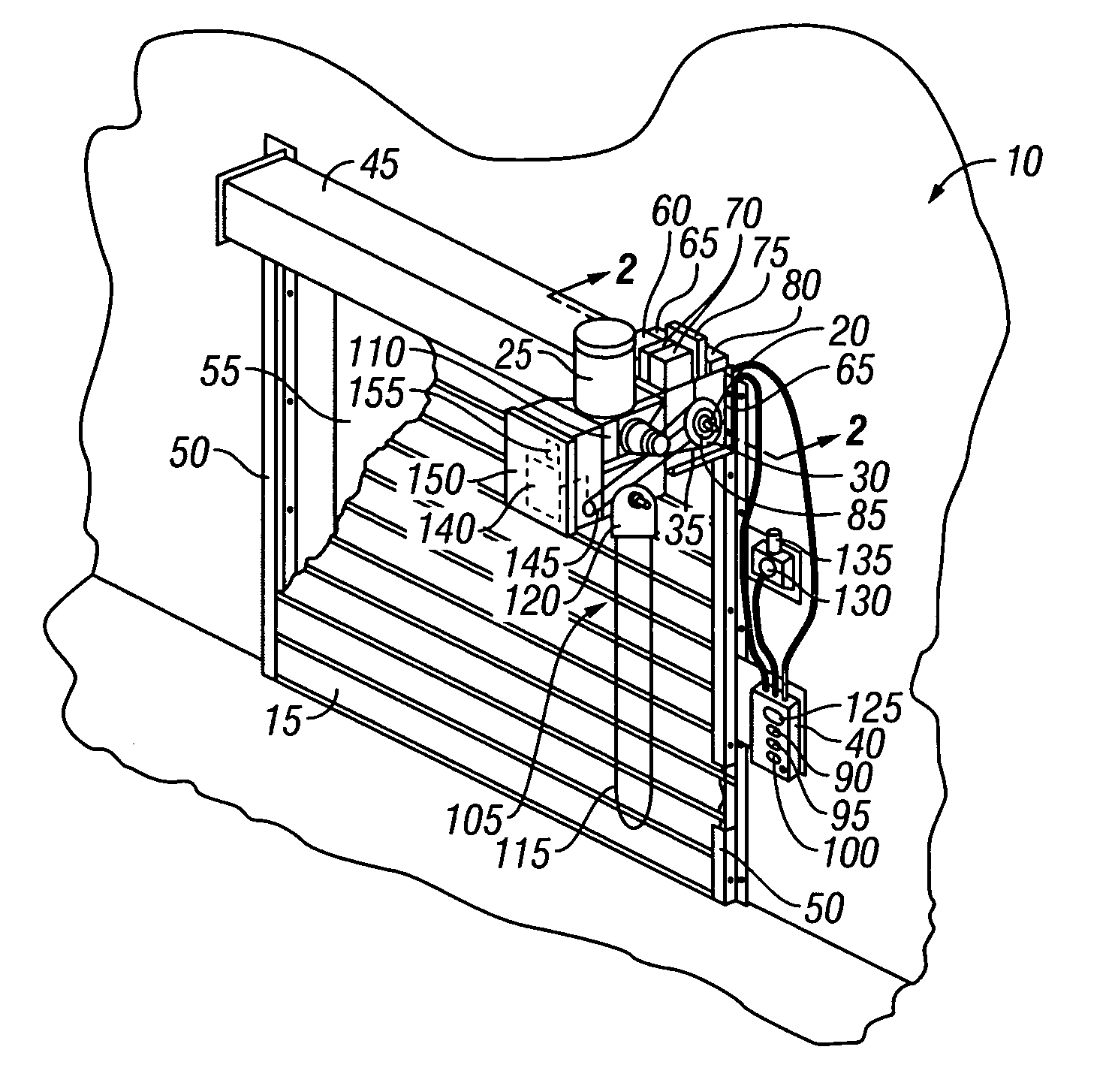
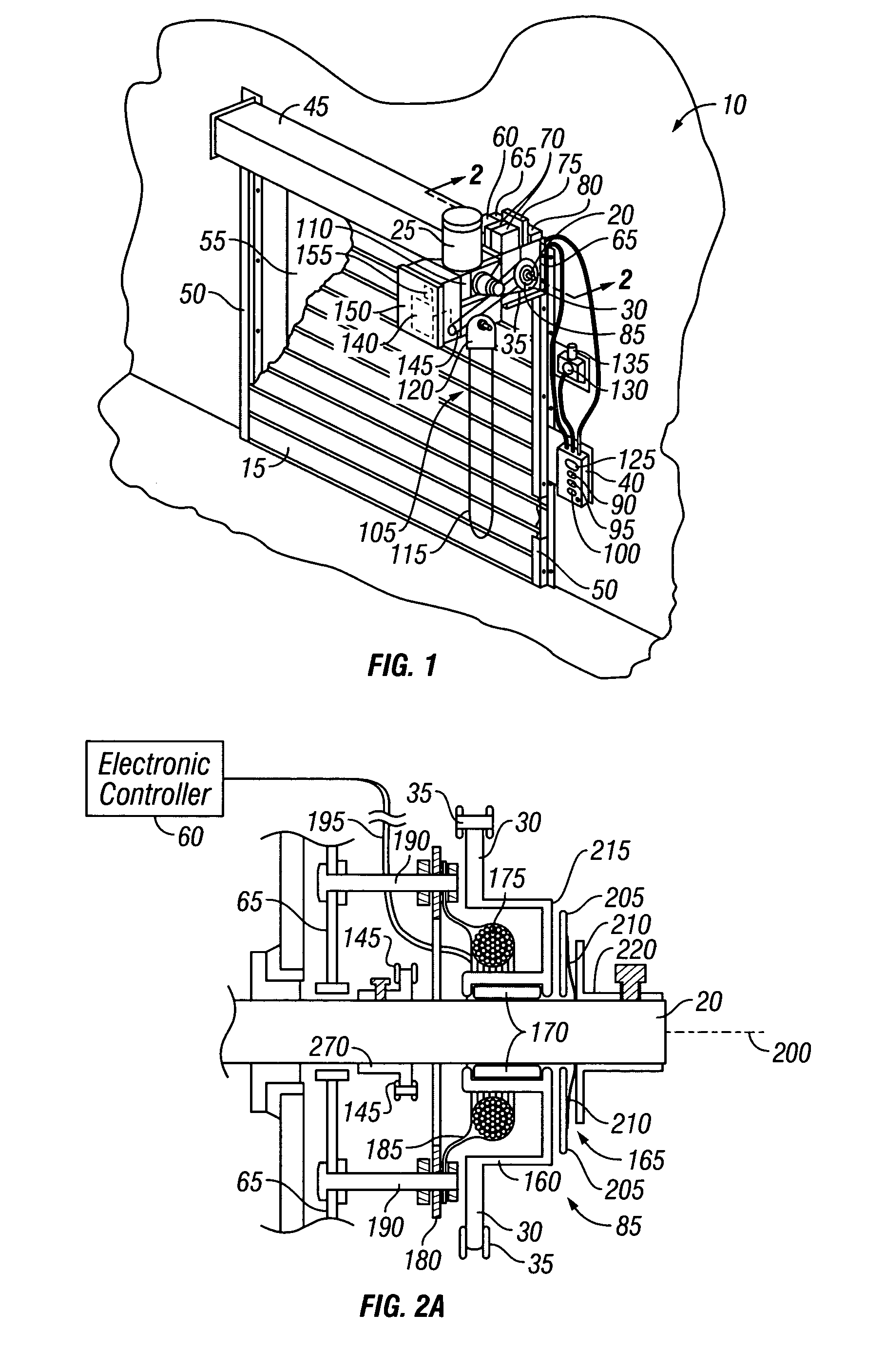
[0030]FIG. 1 is a perspective view of a fire door incorporating a fire door control system 10 in accordance with an embodiment of the present invention. The fire door includes a rollable door 15 supported on an axle 20. The axle 20 is rotated by a drive input comprising a motor 25 that drives a sprocket 30 by a chain 35. The motor 25 is controlled by pressing buttons on a user interface device in the form of a control panel 40. Alternatively, the user interface device could include radio controls, for example, on a remote control device. Some examples of communications connection may include, without limitation, electronic or other data transferring cable (including optical as well as electrical), radio frequency wave transmissions including cellular frequency transmissions as well as microwave, satellite dish frequencies, etc., phone lines (again both optical and electrical), “Bluetooth” technology transmissions, and the like, such as is common with remote communication systems.

[00...


PUM


Abstract

A fire door control system permits user input during regular use and during alarm conditions. The system utilizes primary and secondary power sources and incorporates a variety of preventive safeguards assuring that functionality of the fire door control system will not be lost. The system utilizes primary power when possible in all alarm conditions. However, during alarm conditions when primary power is lost or when a hand crank hoist remains dangerously engaged, the system is bumplessly connected to a secondary power source and a fire door of the system is closed with the aid of a clutch that directly connects the drive input with an axle that supports the fire door. The clutch pulses on and off to control the descent of the door. The system includes an electronic controller for coordinating the operation of elements of the system and for implementing a method of controlling a fire door system.

Description

BACKGROUND OF THE INVENTION[0001]1. Technical Field[0002]This invention generally relates to a fire door control system and more specifically to a method of controlling a fire door and a fire door control system that remains active before, during, and after an alarm condition. The fire door control system of the present invention maintains control of the fire door in some situations by a clutch.[0003]2. State of the Art[0004]The fire door control systems of the past have largely incorporated fusible links that are activated by the heat of a fire when it reaches the fire door. Thus, the fire doors of the past are generally placed in an irreversible alarm mode that is passive since it does not require or respond to input from a person trying to actively stop or otherwise control the fire door. These fire doors require a specialist to come to the site of the door to reset the door and to set the limits for the system. Other fire doors of the past have incorporated other release means t...

Claims


Application Information

Patent Timeline
Patent Type & Authority Patents(United States)
IPC IPC(8): E05F15/20A62C2/24E06B9/74G08B29/00
CPCE06B9/74A62C2/16A62C2/247E05Y2201/246E05F15/70E05Y2900/134E05Y2201/216E05Y2201/462E05Y2201/21E05Y2900/00E05Y2900/106
Inventor EVANS, ROB JASON
Owner OVERHEAD DOOR
Why Eureka
Try Eureka