
Reverse-image identification card printer

a reverse-image identification and printer technology, applied in printing, other printing apparatus, etc., can solve the problems of complicated devices of reverse-image identification card printers, achieve the effects of simplifying the use of printers, improving printer reliability and print quality, and reducing the size of printers

Inactive Publication Date: 2005-04-14
FARGO ELECTRONICS INC
View PDF18 Cites 34 Cited by
  • Summary
  • Abstract
  • Description
  • Claims
  • Application Information

AI Technical Summary

Benefits of technology

[0005] The present invention is generally related to a reverse-image identification card printer. Aspects of the present invention operate to improve printer reliability and print quality, simplify the use of the printer, and reduce the size of the printer, as well as provide other advantages over the printers of the prior art.
[0008] Yet another aspect of the present invention is directed to a method of calibrating tension in a ribbon of a printer that includes first and second rolls that support the ribbon and a sensor for detecting rotation of the first roll. In the method, the second roll is rotated to wind the ribbon thereon and thereby eliminate slack in a section of the ribbon extending between the first and second rolls. Next, rotation of the first roll caused by tension in the section of the ribbon is sensed with the sensor. Finally, the calibration of the tension in the ribbon is completed when the rotation of the first roll is detected by the sensor.

Problems solved by technology

Such reverse-image identification card printers are complicated devices and improvements are in continuous demand.

Method used


Image

  • Reverse-image identification card printer
  • Reverse-image identification card printer
  • Reverse-image identification card printer

Examples


Embodiment Construction

[0026] ID Card Printer Overview

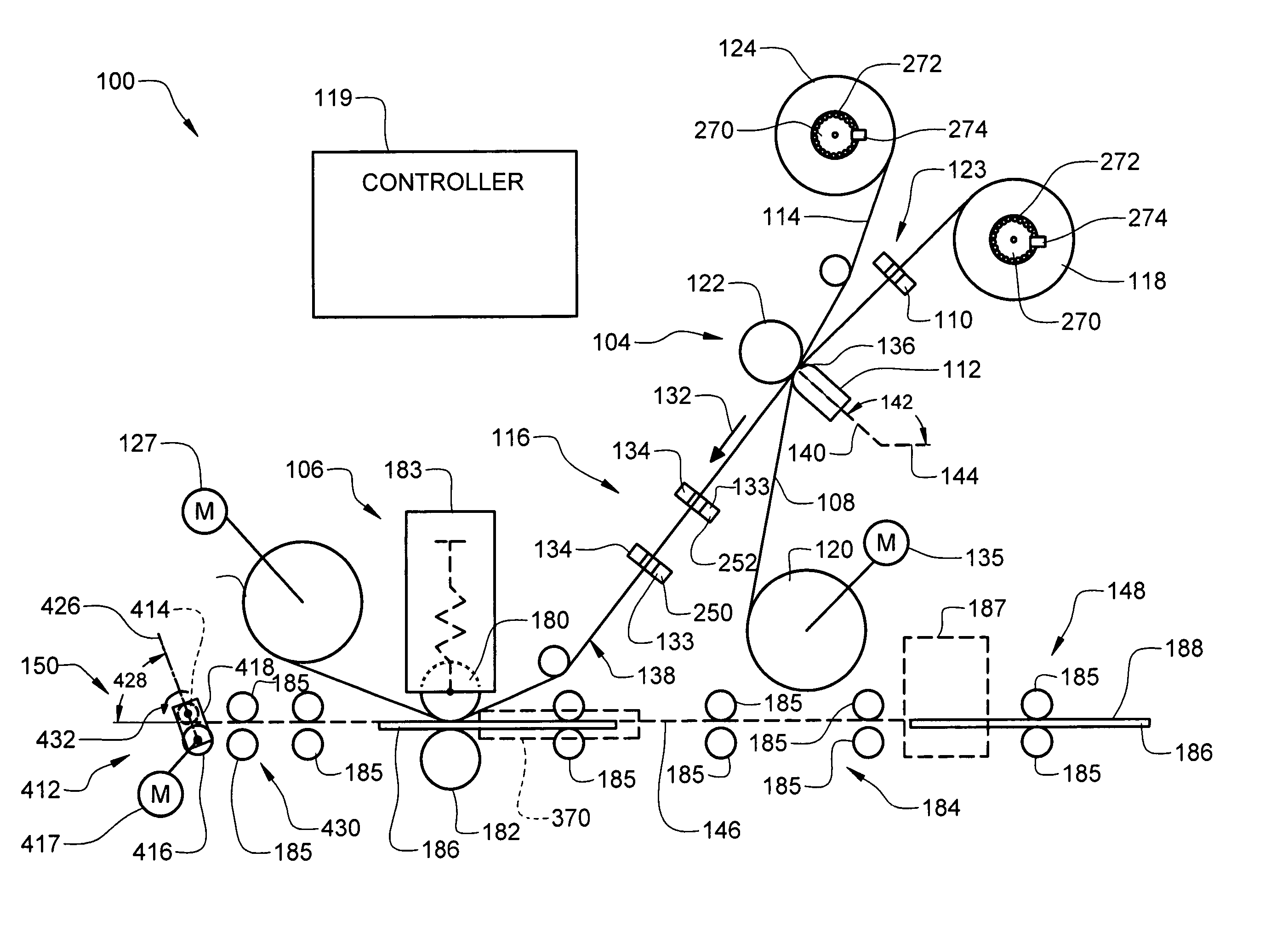
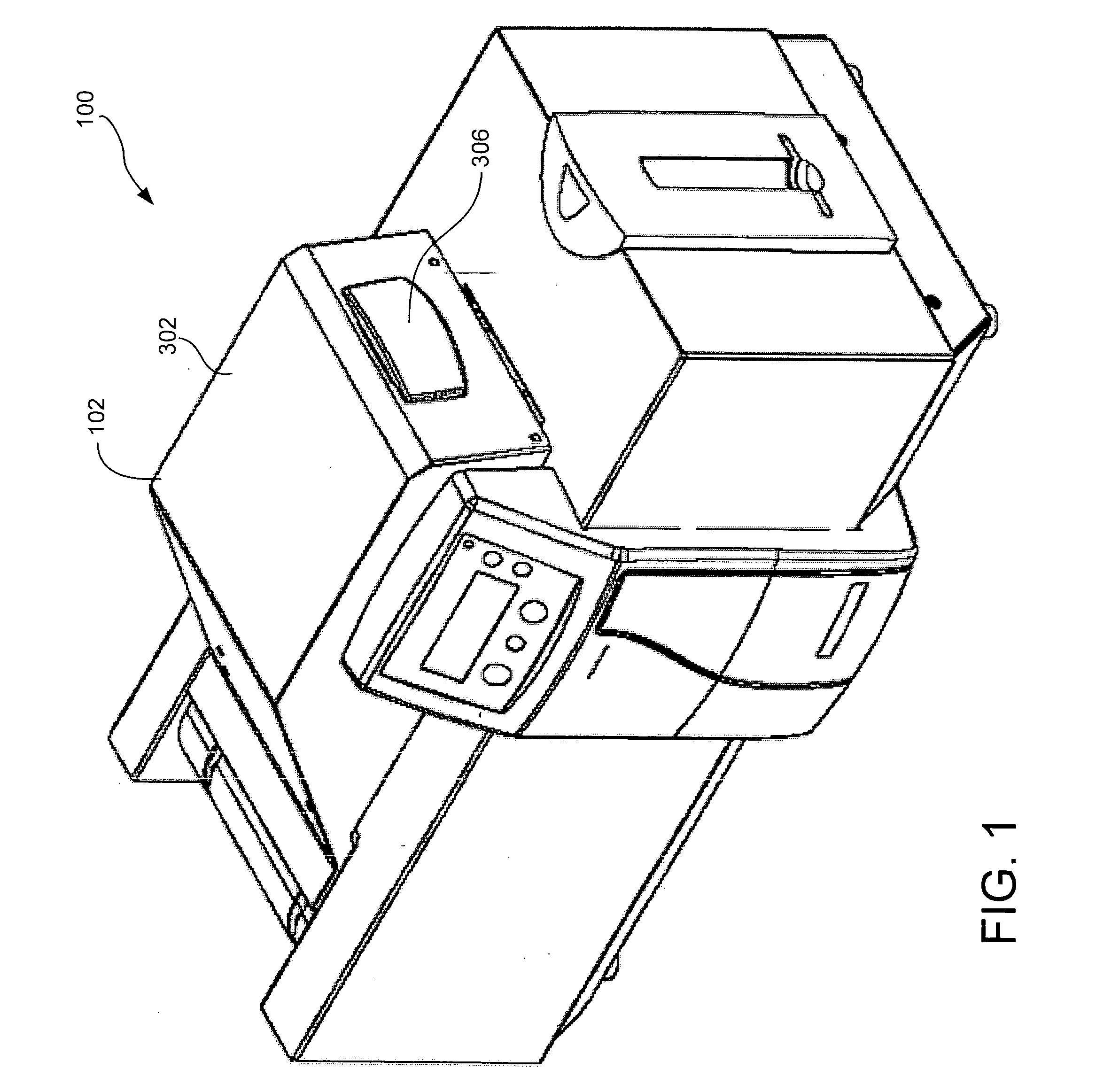
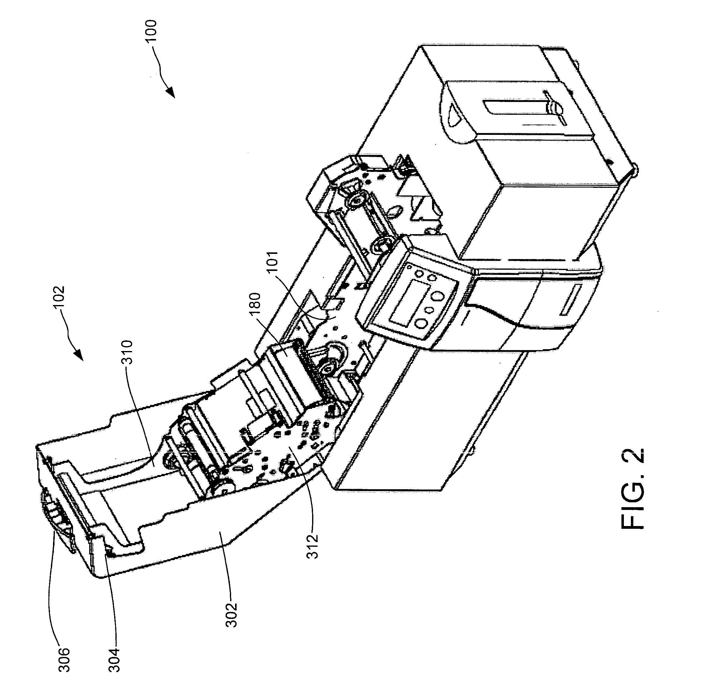
[0027]FIGS. 1 and 2 are perspective views of an exemplary identification card printer 100 having a swing arm assembly 102 respectively in closed and opened positions, in accordance with embodiments of the invention. In accordance with one embodiment of the invention, the printer 100 is a reverse-image printer that operates in a similar manner as that discussed in U.S. Pat. No. 6,261,012, which issued Jul. 17, 2002 and is assigned to Fargo Electronics, Inc. of Eden Prairie, Minn. However, as will be clear to those skilled in the art, while some aspects of the present invention relate specifically to reverse-image printers, others can be useful in both reverse-image printers and printers that print images directly to cards using thermal printheads, inkjet printheads, and other types of conventional printing mechanisms.

[0028]FIG. 3 is a schematic diagram illustrating various components of the printer 100, and FIGS. 4 and 5 are side views of the printer ...


PUM


Abstract

Methods of the present invention relating to an identification card printer include a method of calibrating a ribbon sensor for detecting transition portions between adjoining panels of a ribbon and a method of calibrating tension in a ribbon. Identification card printers in accordance with embodiments of the invention include a sensor positioned downstream of a printhead relative to a feeding direction of a ribbon; support for a printhead that is moveable between print and withdrawn positions; a swing frame supporting a first roll of a ribbon for rotation about an axis about which the swing frame pivots; an adjustable card guide in line with a print path; and a card bender including a pinch roller assembly having first and second rollers, axes of rotation of which are aligned in a plane that is non-perpendicular to a card path.

Description

[0001] The present application claims the benefit of U.S. provisional patent application Ser. No. 60 / 502,535, filed Sep. 12, 2003, the content of which is hereby incorporated by reference in its entirety.BACKGROUND OF THE INVENTION [0002] The present invention generally relates to an identification card printer. Some aspects of the present invention relate to reverse-image identification card printers. [0003] Reverse-image identification card printers generally utilize an intermediate transfer film or ribbon on which an image is printed by a printhead. The printhead is typically a thermal printhead that operates to heat different colored dye panels of a thermal print ribbon to transfer the colored dye from the print ribbon to a panel of transfer film and form the image thereon. The printed image on the transfer film is then registered with a card or other substrate and the image is transferred to a surface of the card from the transfer film. [0004] Such reverse-image identification ...

Claims


Application Information

Patent Timeline
Patent Type & Authority Applications(United States)
IPC IPC(8): B41J13/12B41J29/02B41J29/393
CPCB41J13/12B41J29/393B41J29/02
Inventor LIEN, BRENT D.GALE, THOMAS G. JR.HOFFMAN, TED M.SKOGLUND, JOHN P.VANDER WOUDE, ANDY A.
Owner FARGO ELECTRONICS INC
Learn More