Ground Fault Detection

a ground fault and fault technology, applied in emergency protective arrangements, testing circuits, instruments, etc., can solve the problems of damage to the generator, affecting the stator iron of the generator, and practically impossible occurrence of phase-to-phase faults in the generator

Active Publication Date: 2009-06-25
HITACHI ENERGY SWITZERLAND AG
View PDF4 Cites 31 Cited by
  • Summary
  • Abstract
  • Description
  • Claims
  • Application Information

AI Technical Summary

Benefits of technology

[0021]By measuring a complex value of the resultant current the injection voltage can be used for frequencies well above 50 Hz, since small changes in resistance now can be measured despite a large capacitance reactance, which will be beneficial for e.g. avoiding electrical interference with existing speed gauges.
[0022]Further, by measuring a complex value of the resultant current a ground fault detection arrangement according to the present invention will also handle all types of grounding methods on generators in a similar way which provides for production advantages.

Problems solved by technology

Ground faults in a generator stator winding are the most frequent internal generator electrical fault, and the most frequent cause of damage to the generator stator and a direct cause of phase-to-phase fault of the generator stator.
A ground fault is caused by physical damage to the stator winding or aging of the insulation of the stator.
Improper operation of ground-fault protection of the stator winding increases the possibility that a ground fault will transform into a phase-to-phase fault, which ultimately will damage the generator.
Thus, the occurrence of phase-to-phase faults in the generator is practically impossible, if the ground-fault protection operates properly.
But even such small currents can cause significant damages to the generator stator iron.
There are three main limitations which influence the length of the stator winding, which is covered by this protection during different operating conditions.
However, the second limitation can be used to improve ground-fault protection dependent on the protection system.
Further, existing injection methods utilizes an injection frequency below 50 Hz, as higher frequencies increases capacitive current making it difficult to detect changes in the resistance used to detect ground faults.

Method used


Image

  • Ground Fault Detection
  • Ground Fault Detection
  • Ground Fault Detection

Examples


Embodiment Construction

[0037]In the following description, for purpose of explanation and not limitation, specific details are set forth, such as particular techniques and applications in order to provide a thorough understanding of the present invention. However, it will be apparent for a person skilled in the art that the present invention may be practiced in other embodiments that depart from these specific details. In other instances, detailed description of well-known methods and apparatuses are omitted so as not to obscure the description of the present invention with unnecessary details.

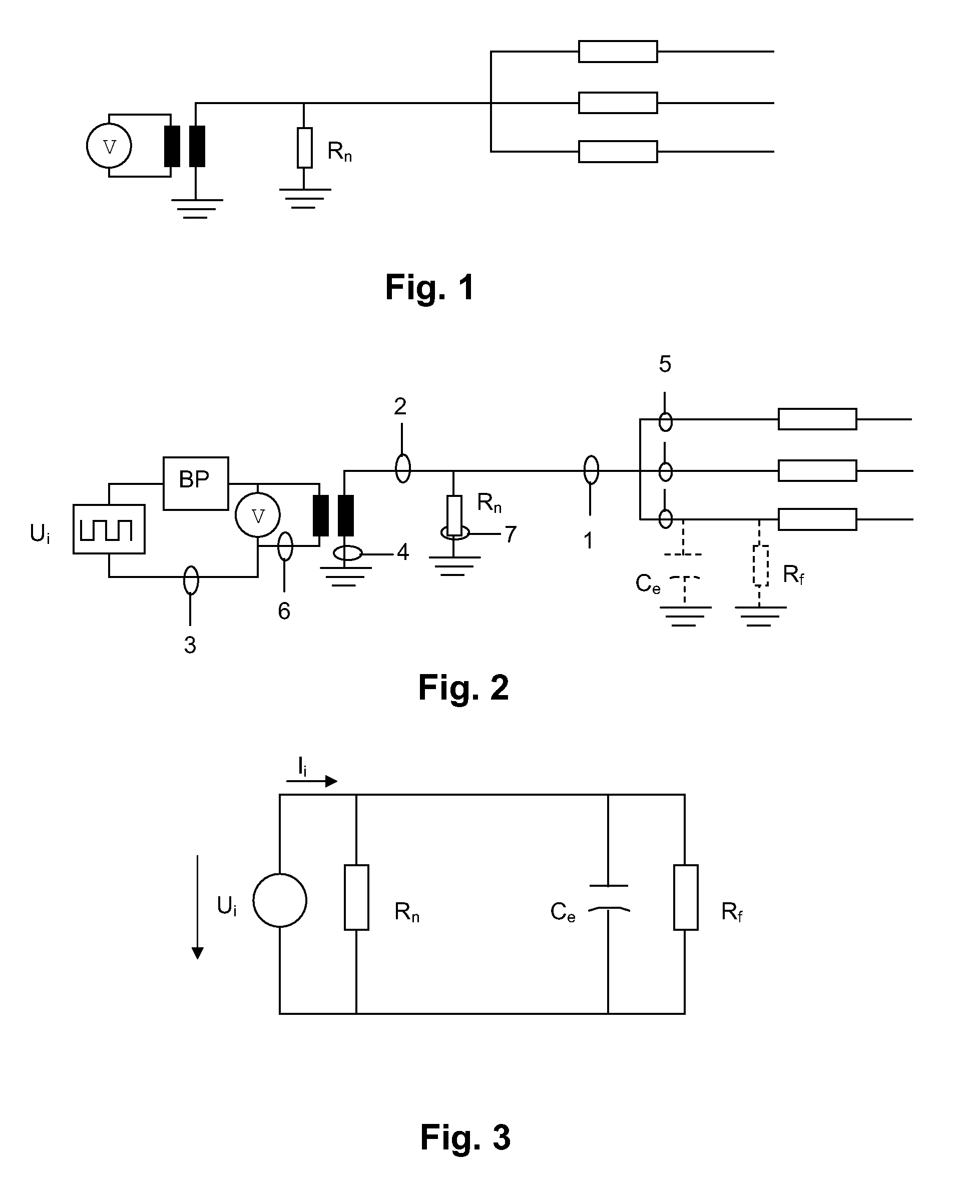
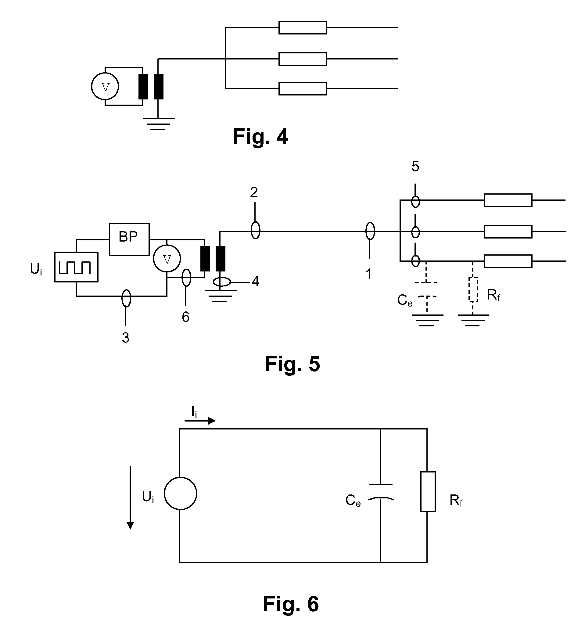
[0038]A first embodiment of the present invention will now be described with reference to FIGS. 1-3.

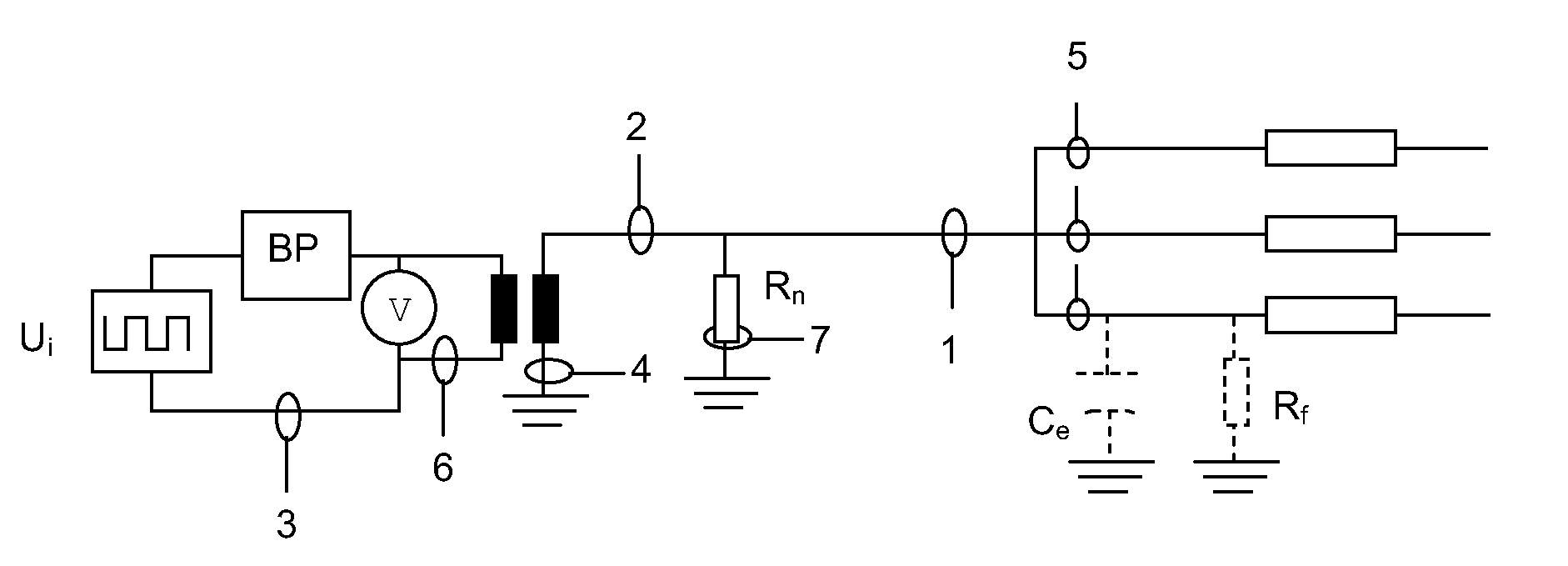
[0039]A stator part of a synchronous three-phase electrical machine, such as a generator, is schematically shown in FIG. 1. The synchronous three-phase electrical machine is Y-connected and is at its neutral point connected to ground. The synchronous three-phase electrical machine comprises a neutral resistor Rn betwe...


PUM


Abstract

The present invention relates to a ground fault detection arrangement for a synchronous three-phase electrical machine, and an electrical system comprising a ground fault detection arrangement and a synchronous three-phase electrical machine. The ground fault detection arrangement injects an off-nominal frequency voltage between a neutral point of the synchronous three-phase electrical machine and ground and measure resultant currents to detect a ground fault.

Description

CROSS-REFERENCE TO RELATED APPLICATIONS[0001]The present application is a continuation of pending International patent application PCT / SE2007 / 000724 filed on Aug. 15, 2007 which designates the United States and claims priority from European patent application 06445061.2 filed on Aug. 18, 2006, the content of which is incorporated herein by reference.FIELD OF THE INVENTION[0002]The present invention relates generally to ground fault detection and more particularly to a ground fault detection arrangement.BACKGROUND OF THE INVENTION[0003]Ground faults in a generator stator winding are the most frequent internal generator electrical fault, and the most frequent cause of damage to the generator stator and a direct cause of phase-to-phase fault of the generator stator. All other electrical faults are always preceded by the ground faults. A ground fault is caused by physical damage to the stator winding or aging of the insulation of the stator. Therefore, stator ground-fault protection is ...

Claims


Application Information

Patent Timeline
Patent Type & Authority Applications(United States)
IPC IPC(8): G01R31/12
CPCH02H1/0038H02H7/06H02H3/17
Inventor JOHANSSON, STEFAN G.FULCZYK, MAREKBENGTSSON, TORDLINDAHL, STUREOLGUIN, GABRIEL
Owner HITACHI ENERGY SWITZERLAND AG
Why Eureka
Try Eureka