Multiplex microparticle system

a microparticle and array technology, applied in the field of arrays of labeled microparticles, can solve the problems of sensitivity and dynamic range, limit their utility, arrays based on different size microparticles are problematic, etc., and achieve the effect of simplifying the creation of multiplex assays

Active Publication Date: 2009-03-24
BECTON DICKINSON & CO
View PDF17 Cites 38 Cited by
  • Summary
  • Abstract
  • Description
  • Claims
  • Application Information

AI Technical Summary

Benefits of technology

[0013]The present invention relates to multidimensional arrays formed from populations of singly dyed microparticles. The use of singly dyed microparticles to form multidimensional arrays greatly simplifies the creation of multiplex assays, yet still provides most of the advantages arrays formed from multiply dyed microparticles.
[0019]The microparticle arrays of the present invention can be used essentially in any application in which multiplex particle arrays are used or are useful, including applications in which the microparticles are used a solid substrates for ligand binding assays or as labeling reagents. A preferred use of the arrays is to implement multiplex binding assays for the simultaneous detection of two or more analytes using, for example, flow cytometry or microscopy. For use in such assays, the microparticles are coated with analyte-specific reagents such that microparticles within a population are coated with reagents having the same known specificity and microparticles in different populations are coated with reagents having different specificities. The identity of the microparticle populations, determined from the microparticle fluorescence measured in the two detection channels, enables identification of the analyte bound to the microparticle through the analyte-specific reagent. One skilled in the art will understand that detection can be carried out using any of a number of different assay formats, including sandwich hybridization formats and competitive assay formats.

Problems solved by technology

Each of the microparticle arrays described above has disadvantages that limit their utility.
Arrays based on different size microparticles are problematical because the amount of capture reagent that can be bound to a microparticle, which affects the sensitivity and dynamic range of the assay, is dependent on the particle size.
Two-dimensional arrays based on differences in the fluorescence intensities of two distinct dyes enable much larger arrays, but are significantly more difficult to manufacture, and increase the difficulty in subsequent data analysis.

Method used


Image

  • Multiplex microparticle system
  • Multiplex microparticle system
  • Multiplex microparticle system

Examples


example 1

Preparation a Microparticle Array

[0055]This example describes preferred methods for preparing a microparticle array for use in flow cytometry.

[0056]The array described herein is intended for use in a detection assay in which the microparticles are coated with an analyte-specific reagent, and a labeled-reporter reagents are used to measure the amount of analyte bound to a microparticle. To maximize sensitivity of the detection assay, it is desirable to label the reporter reagents with a particularly bright fluorophore, preferably phycoerythrin (PE), which has an emission maximum at 578 nm. Thus, the array is prepared assuming that an appropriate detection channel is reserved for measuring the PE-labeled reporter reagents.

1. Detection Channels

[0057]The detection channels used to measure the microparticle fluorescence are selected from the channels available using a flow cytometer. Preferred flow cytometers are the BD FACSCalibur™ flow cytometer and the BD FACSArray™ flow cytometer (BD...

example 2

29-Population Array

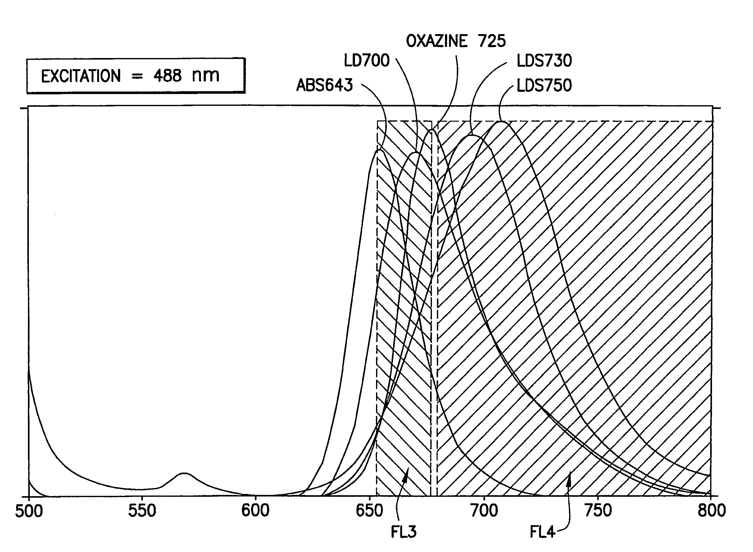
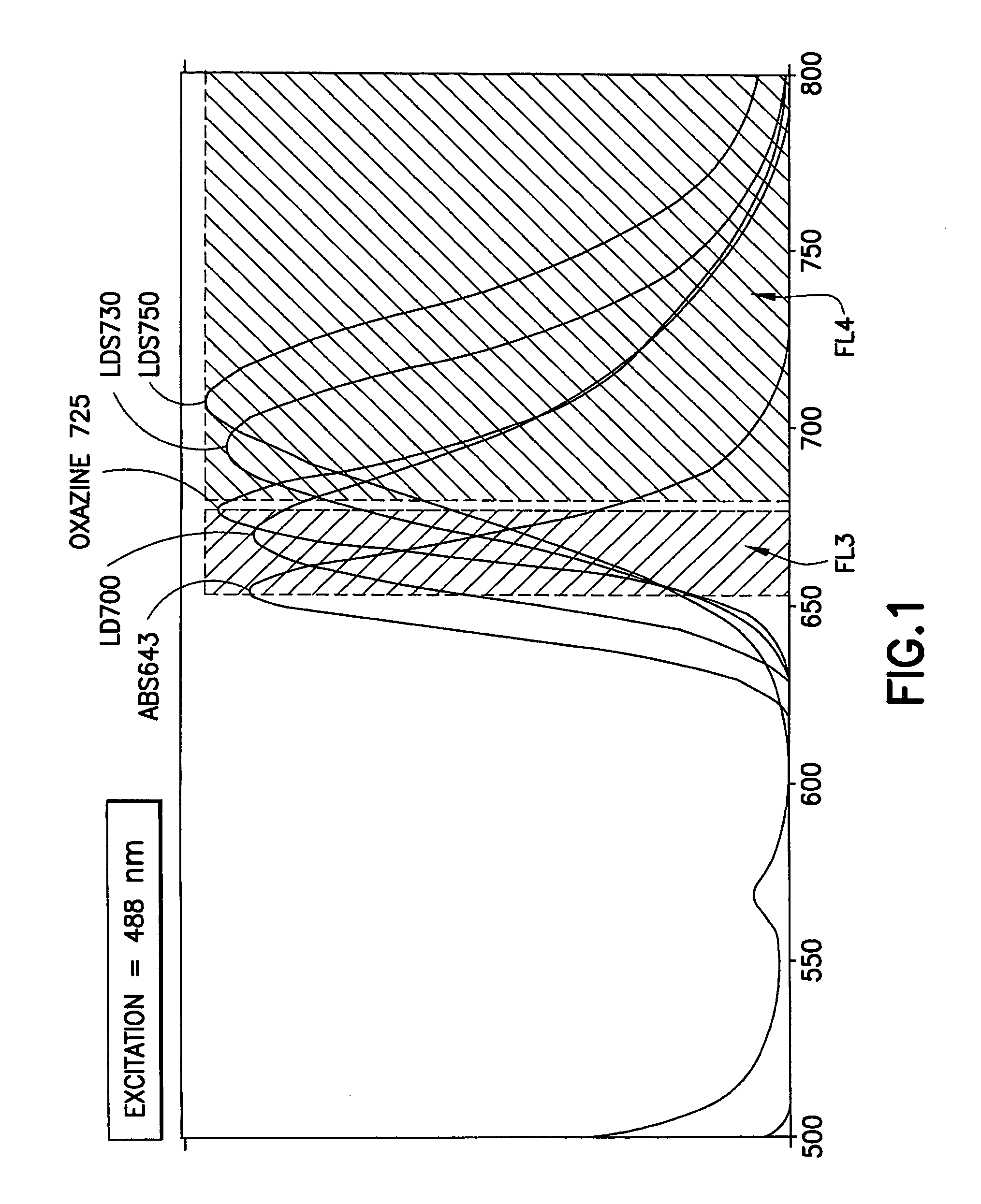
[0080]Bead subsets were prepared essentially as described in Example 1 using each of the dyes listed in the table, below. All dyes were obtained from Exciton (Dayton, Ohio). Excitation and emission maxima, which were measured in either ethanol, methanol, or dichloromethane, are known to be somewhat dependent on the solvent used for the measurements, and slightly different results may be obtained using different solvents.

[0081]

DyeExcitation MaxEmission MaxPopulations used in arrayLD7006476737LDS7306146954LDS7505727043LDS7515427001Oxazine 7256456766ABS6436406558

[0082]The emission spectra of these dyes (with the exception of LDS751) are shown in FIG. 1. Also shown are the boundaries of the detection channel defined using a BD FACSArray flow cytometer.

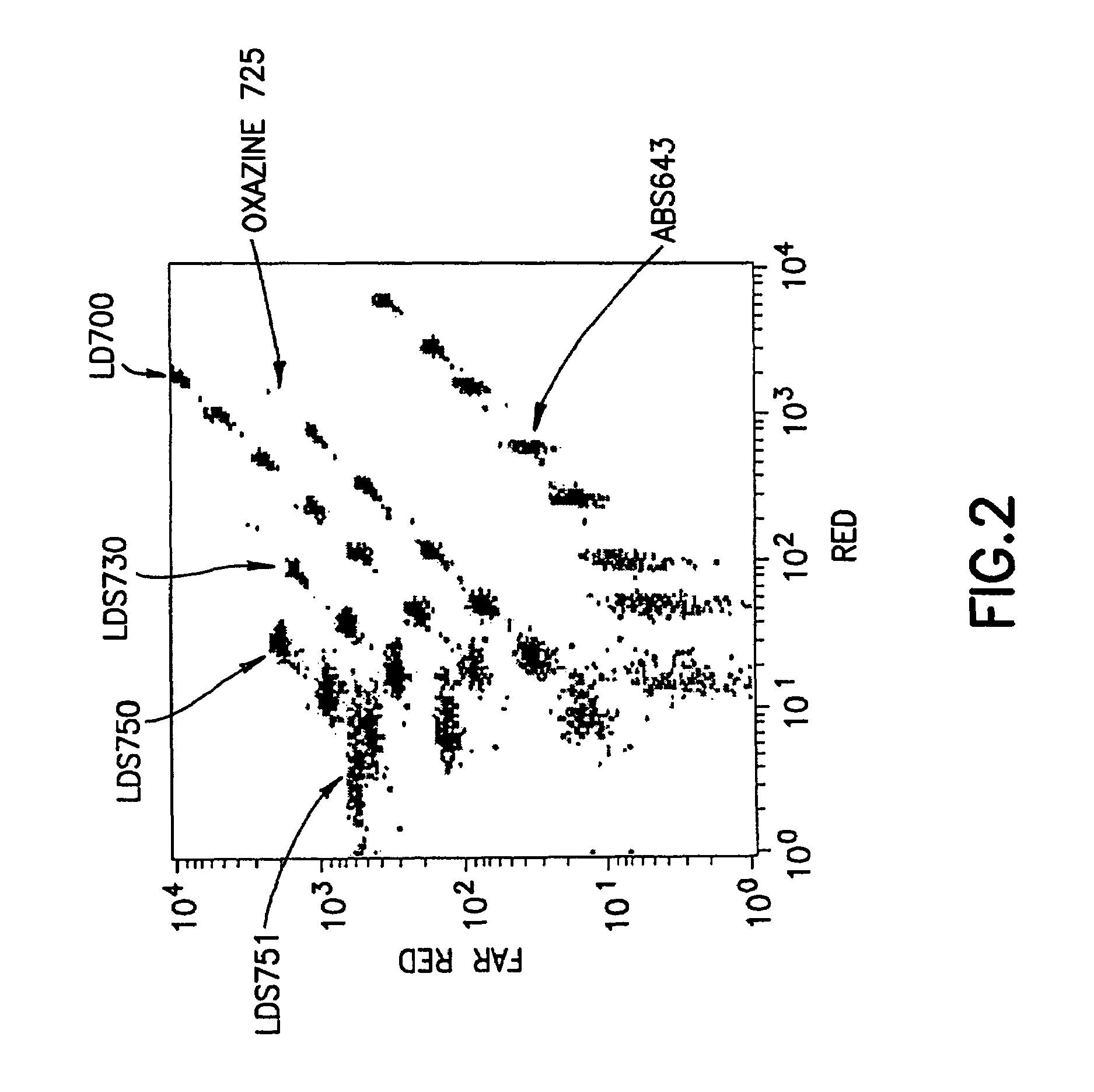
[0083]Sets of dyed beads, each containing bead populations dyed with different amounts of one of the dyes, were combined and were analyzed on a BD FACSArray flow cytometer, as described above. Bead populations that were ...

example 3

Extended Array

[0085]The bead array described in Example 2 was incrementally extended by the inclusion of a bead set dyed using LDS765 (Exciton, Dayton, Ohio), prepared essentially as described above. The measured excitation and emission maxima for the dye are shown in the table, below:

[0086]

DyeExcitation MaxEmission MaxPopulations used in arrayLD7655957523

[0087]For this analysis, the sets of dyed beads, were analyzed on a BD FACSCalibur flow cytometer, as described above. Bead populations from the set dyed with LDS765 were selected such that the populations were both uniquely distinguishable and simultaneously on-scale relative to the bead populations in the previously constructed array. Three populations could be added to the 29-population array. FIG. 3 shows a dot-plot (FL3×FL4) of the selected bead array containing 32 distinguishable bead populations.

[0088]The emissions of the bead populations in the PE-channel (FL2) also were measured (results not shown), and minimal spillover w...


PUM

PropertyMeasurementUnit
diameteraaaaaaaaaa
diameteraaaaaaaaaa
diameteraaaaaaaaaa

Abstract

Arrays of microparticle populations, each population labeled with a single fluorescent dye, are provided for use in multiplex assays. The populations form a virtual multidimensional array wherein each microparticle is identified by fluorescence intensity in two different fluorescence detection channels. The arrays are useful in a variety of assays, including multiplex, multi-analyte assays for the simultaneous detection of two or more analytes by, for example, flow cytometry, and a labeling reagents in, for example, microscopy. The use of singly-dyed microparticles to form multidimensional arrays greatly simplifies the creation of multiplex assays.

Description

CROSS REFERENCE TO RELATED APPLICATIONS[0001]This application claims priority to U.S. provisional application No. 60 / 673,471, filed Apr. 20, 2005, the disclosure of which is incorporated herein by reference.BACKGROUND OF THE INVENTION.[0002]1. Field of the Invention[0003]The present invention relates to arrays of labeled microparticles. Such arrays are particularly useful in multiplex assays, such as biological detection assays and, more particularly, in the fields of flow cytometry and fluorescence microscopy.[0004]2. Description of Related Art[0005]Flow cytometers are well known analytical tools that enable the characterization of particles on the basis of light scatter and particle fluorescence. In a flow cytometer, particles are individually analyzed by exposing each particle to an excitation light, typically one or more lasers, and the light scattering and fluorescence properties of the particles are measured. Particles, such as molecules, analyte-bound beads, individual cells,...

Claims


Application Information

Patent Timeline
Patent Type & Authority Patents(United States)
IPC IPC(8): G01N33/543
CPCG01N33/54313G01N33/582G01N33/585Y10S435/973Y10T436/101666Y10T436/112499Y10T436/110833
Inventor MEHRPOUYAN, MAJIDRECKTENWALD, DIETHER J.VARRO, RUDOLF
Owner BECTON DICKINSON & CO
Why Eureka
Try Eureka