Condensing Water Heater and Condensation Control System

a water heater and control system technology, applied in water heaters, central heating components, sustainable buildings, etc., can solve problems such as increasing design complexity, and achieve the effects of preventing condensation of water, maximizing heat, and rapid response to hot water demand

Active Publication Date: 2018-08-09
BOCK WATER HEATERS
View PDF7 Cites 14 Cited by
  • Summary
  • Abstract
  • Description
  • Claims
  • Application Information

AI Technical Summary

Benefits of technology

[0006]It is an object of the present invention to provide a condensing water heater which is controlled to maximize the heat which can be extracted by condensing water vapor in the combustion gases while still providing rapid response to hot water demand.
[0007]It is an object of the present invention to prevent condensation of water in a flue system of a condensing flue water heater before the condensing section of the flue.

Problems solved by technology

This increases the complexity of the design due to the corrosive nature of liquid water as opposed to steam.

Method used


Image

  • Condensing Water Heater and Condensation Control System
  • Condensing Water Heater and Condensation Control System
  • Condensing Water Heater and Condensation Control System

Examples


Embodiment Construction

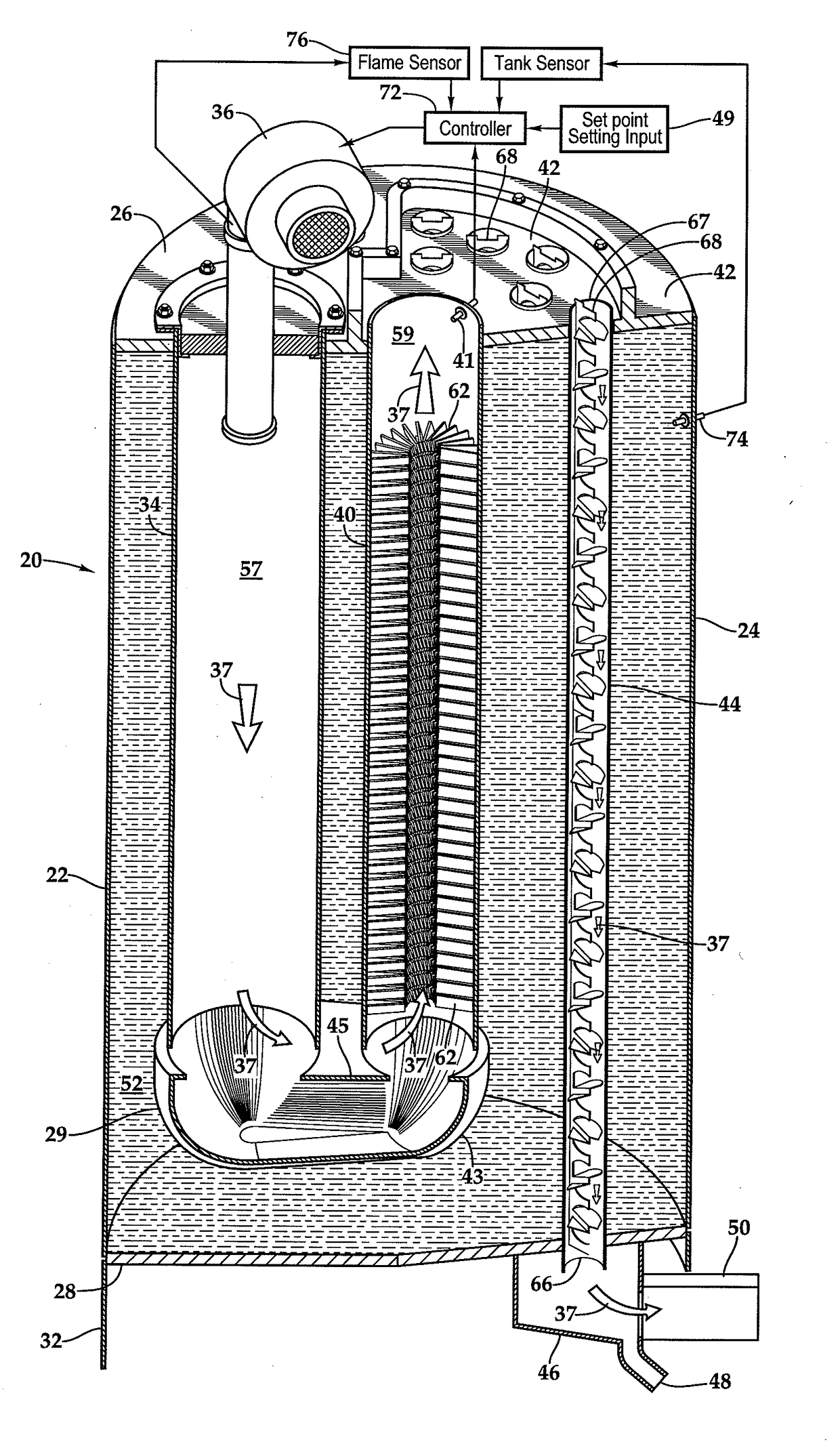
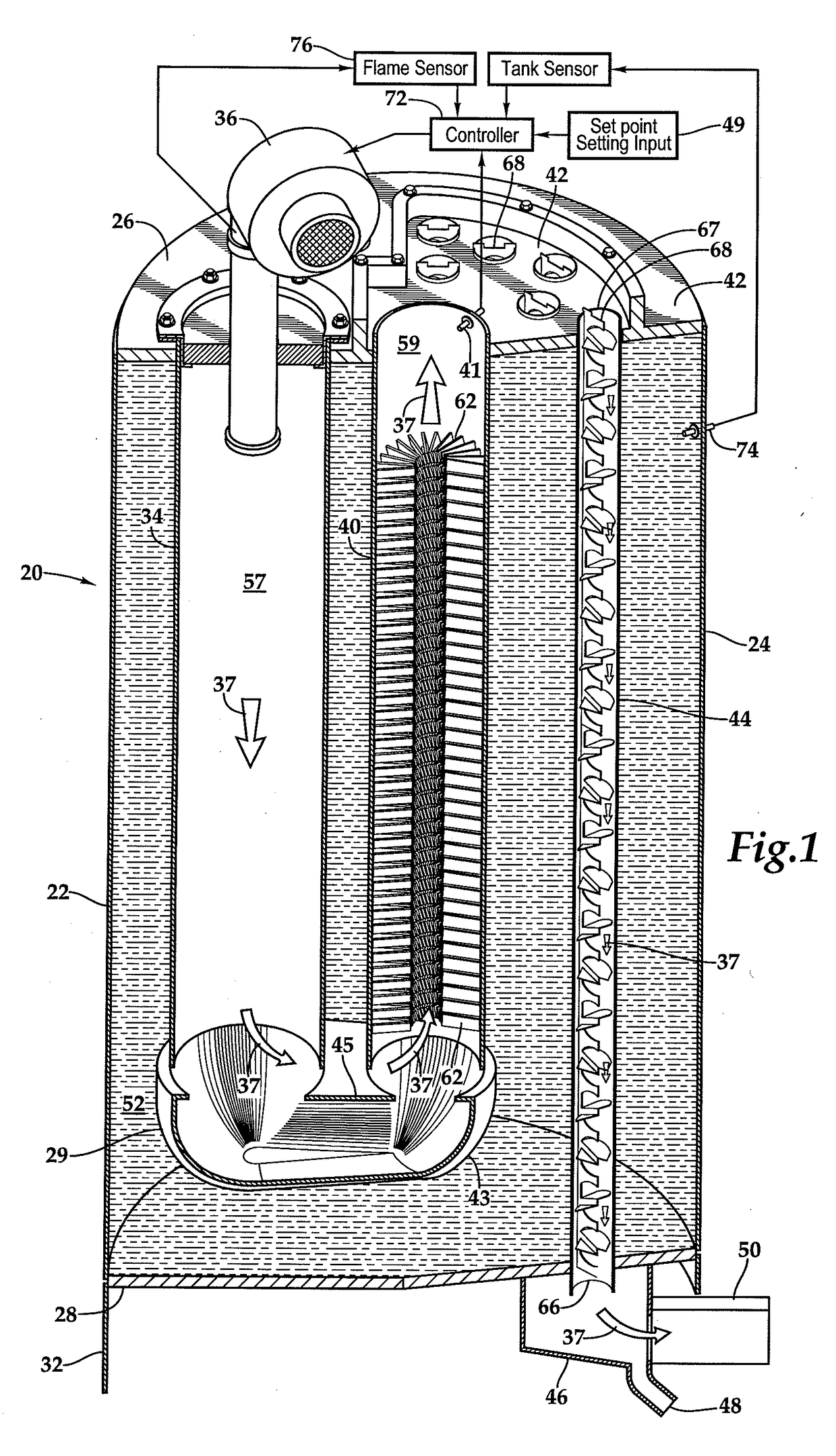
[0015]Referring more particularly to FIGS. 1-6 wherein like numbers refer to similar parts, a water heater 20 is shown schematically in FIG. 1. The water heater has a tank 22 formed of a mild steel cylindrical outer shell 24 to which are welded two circular domes, comprising an upper dome 26, and a lower dome 28. Mounted below the water tank 22 is a downward continuation of the outer shell which is a cylinder forming a stand 32. Three types of cylindrical flues or heat exchanging pipes, a first flue 34, second flue 40, and one or more third flues 44 arranged between the upper dome 26 and the lower dome 28 within the water tank 22 such that the axes of the flues are parallel to an axis defined by the outer shell 24 of the tank. A power burner 36 is mounted to the first flue 34 and is fired downwardly from the upper dome 26. The burner 36 has a fan (not shown) driven by a motor 70 as shown in FIG. 4. The speed of the motor 70 drives the fan to supply approximately 20%-30% excess combu...


PUM


Abstract

A water heater with two non-condensing flues and a condensing flue(s) having a system to prevent condensation in the non-condensing flue(s). The downwardly extending first flue is connected by a 180 degree connector to an upwardly extending second flue. Between the non-condensing and the condensing flues is positioned a temperature sensor. A controller receives input from the temperature sensor and is connected to the burner to control the minimum power setting and duration so as to prevent the combustion gases from falling below a temperature at which water will condense at the temperature sensor so no condensation occurs in the first two flues. Burner power settings are minimized near a water tank setpoint to improve efficiency by increasing condensation.

Description

BACKGROUND OF THE INVENTION[0001]The present invention relates to water heaters in general, and more particularly to water heaters with multi-flues, at least one of which is condensing.[0002]Heat exchange between a liquid and a gas is a process which has many industrial and domestic applications. Perhaps one of the most widely used applications of heat exchange between a gas and a liquid is in heating water. Typically a water heater has a tank which holds the water to be heated, and a burner producing combustion gases. The water is heated by the combustion of fuel with air in the burner to produce the combustion gases which heat the water in the tank by passing through one or more flues or tubes which extend through the water tank. Two considerations which are paramount in the design of a water heater are durability and efficiency. To conserve resources and limit the production of carbon dioxide, efficiency has become paramount in all devices using combustion to generate heat. Appro...

Claims


Application Information

Patent Timeline
Patent Type & Authority Applications(United States)
IPC IPC(8): F24H9/20F24H1/20F24H8/00F24H9/00F24H9/18
CPCF24H9/2035F24H1/205F24D2220/042F24H9/0026F24H9/1836F24H8/00Y02B30/00F24H15/20F24H15/223F24H15/35F24H15/112F24H15/235F24H15/36F24H15/174
Inventor STEINHAFEL, MICHAEL B.GOURLIE, JONATHAN
Owner BOCK WATER HEATERS
Why Eureka
Try Eureka