Furnace assembly

a technology for furnaces and furnaces, applied in furnaces, charge manipulation,foundry moulding apparatuses, etc., can solve the problems of affecting the later molding process, and consuming a lot of time, so as to achieve the maximum heating of molds, improve heat control, and melt wax as quickly as possibl

Active Publication Date: 2017-11-07
PREMIER FURNACE SPECIALISTS INC
View PDF12 Cites 0 Cited by
  • Summary
  • Abstract
  • Description
  • Claims
  • Application Information

AI Technical Summary

Benefits of technology

[0006]Thus, several advantages of one or more aspects of the invention include that the wax drippings and unburnt wax vapors are drawn down through the passageway into the lower chamber while igniting the vapors and wax in the lower chamber in a controlled manner. The burning wax helps to reduce the amount of fuel required to heat the furnace. The unique design and downward flow of vapors and wax substantially prevents the wax from burning proximate to the investment casting molds and contaminating the inner surfaces of the casting molds.
[0008]The lower chamber includes a divider extending along the majority of the length of the lower chamber between the first end and the chimney, and wherein the divider divides the lower chamber into two longitudinally extending chambers. The at least one burner extending into the lower chamber includes a first lower burner aligned with one of the two longitudinally extending chambers and a second lower burner aligned with the other of the two longitudinally extending chambers. These are larger burners and configured to assist with creating the venture effect in the lower chamber. The first and second lower burners are located on the first end under the door. More specifically, the first and second lower burners are each configured to force hot air, gases, vapor and wax from the first section through the second section and to the third section of the lower chamber and to the at least one chimney. The burned wax and hot air then passes through the opening and out the chimney, where a chimney burner may burn any un-combusted materials, and an air system may further improve draw and dilute any emissions. More specifically, the first and second lower burners in combination with the second section create a venturi effect in the first section by drawing air from the upper chamber through the passageway to the lower chamber.
[0010]The lower chamber in the first and second sections are divided by a longitudinally extending divider. The divider is configured to reduce the cross sectional area of the lower chamber into smaller sections, thereby improving the venture effect desired. The third section is substantially free from the longitudinally extending divider, which improves air flow to the chimney opening. The third section further includes in the lower chamber a laterally extending barrier aligned with the opening on the chimney and wherein the opening extends past both sides of the barrier. The barrier forces the gas toward the opening on the chimney, and also allows the opening on the chimney to draw air from the force section (on the opposite side of the barrier as the third section), and thereby create a negative pressure in the fourth section, such that the second end may have an open opening, not covered by a door and use the entering ambient air to cool the products on their trays that are passing through the fourth section, without interfering with the heating process occurring in the first and second sections. In addition, the lower chamber does not extend into the fourth section and wherein the fourth section terminates in an opening at the second end, which is not covered by a door.
[0012]In addition, the furnace includes as the at least one upper burner, a plurality of upper chamber burners on a first side and a plurality of upper chamber burners on an opposing second side in the second section, and wherein the plurality of upper burners on the first side are staggered relative to the plurality of upper chamber burners on the second side. These plurality of staggered burners are in the second section, but the first section may also include a plurality of upper chamber burners, although these may not be staggered to maximize heating of the molds after entry and closure of the door, to have the wax melt out of the molds as quickly as possible. The passageways are located within the first section, and allow wax vapors to be pulled into the lower chamber, and liquid wax to drip down through the holes on the trays, through the passageways, where the lower burner ignites such wax and wax vapors. The inner side of the outer housing is lined with furnace bricks or tiles in the upper chamber and the lower chamber in the first section. The bricks or tiles may form an arched overhead shape, while defining the lower floor of the upper chamber, which is also the roof of the lower chamber. In the second section, the upper chamber is fiber lined and furnace brick lined in the lower chamber in the second section. Partitions extend downward from the roof of the upper chamber, including a first partition the divides the first and second sections. The partitions allow better heat control and more consistent temperatures as the investment castings move from the first end to the second end. The second section may include multiple partitions, and a partition may divide the second and third sections as well as the third and fourth sections.

Problems solved by technology

This necessitates a means to collect and recycle or dispose of the recovered wax, which is expressive and time consuming, and may require cooling of the furnace at regular intervals, which is also expensive and time intensive.
Additionally, these furnace assemblies heat and dewax the molds in a single operation, which may allow unburnt wax and wax vapor to accumulate on the investment casting molds in the furnace assembly or reach ignition temperature before it is fully melted and absent from the molds.
One problem with these types of furnaces is that they allow the wax to burn and contaminate the inner surfaces of the casting molds as well as the carriers, such as trays.
In addition, any wax burned in the same chamber or on the investment casting molds may leave behind carbon deposits that are undesired and may negatively affect the later molding process.

Method used


Image

  • Furnace assembly
  • Furnace assembly
  • Furnace assembly

Examples


Embodiment Construction

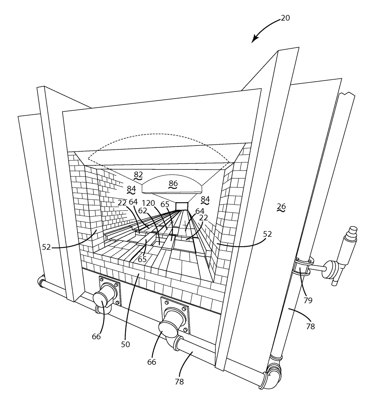
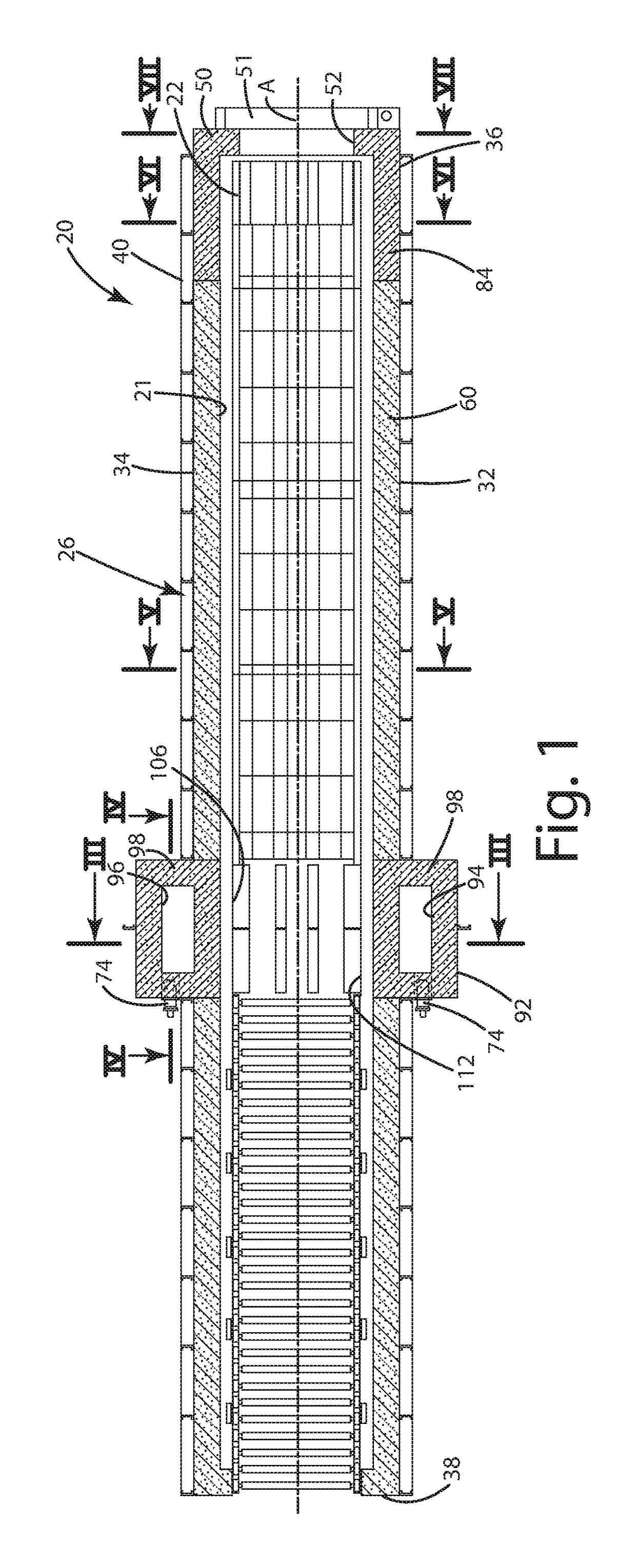
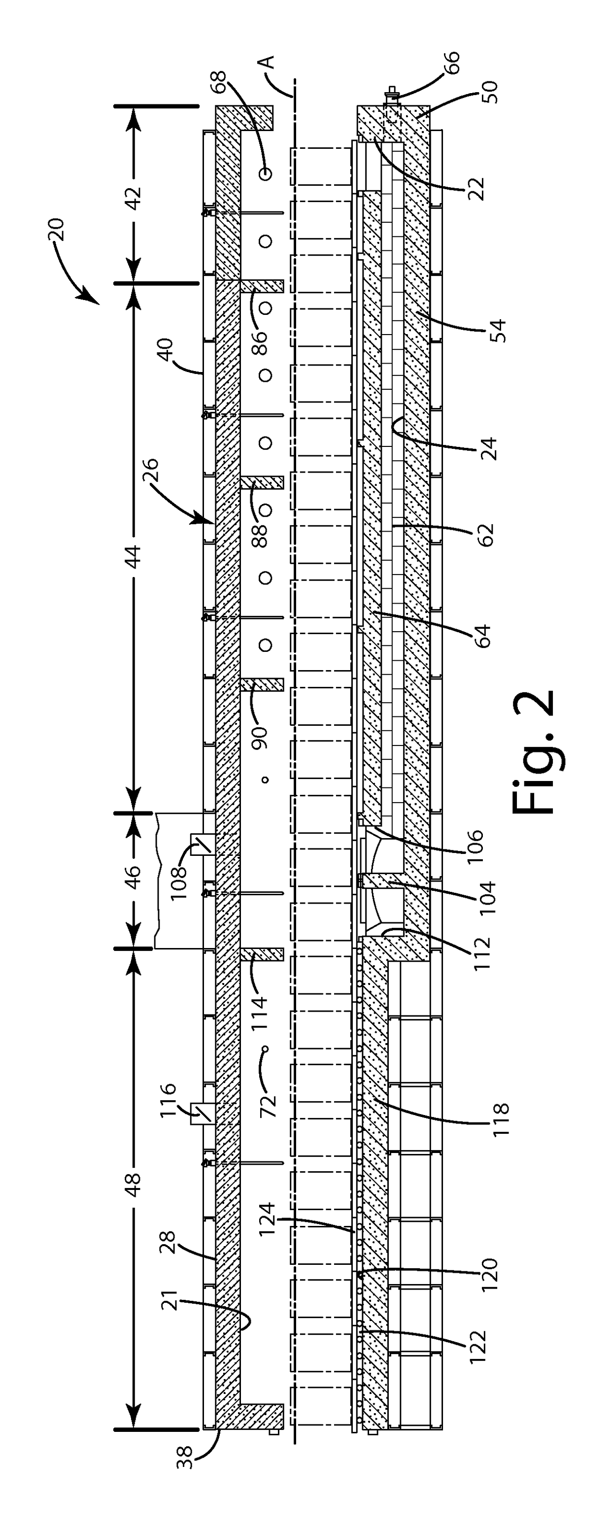
[0028]Referring to the Figures, wherein like numerals indicate corresponding parts throughout the several views, a furnace assembly 20 constructed in accordance with the subject invention is shown in the Figures. The furnace assembly 20 is generally intended to be used for heating and dewaxing investment casting molds; however, it should be appreciated that the furnace assembly 20 could be used for heating of various other items.

[0029]The furnace assembly 20 includes an outer housing 26 divided into an upper chamber 21 and at least one lower chamber 24. At least one burner 66, 68, 72, 74 is disposed in the housing 26 for heating the upper chamber 21 and heating the at least one lower chamber 24. At least one chimney 94, 96 is connected to the housing and to the at least one lower chamber 24 for exhausting air and vapors from the lower chambers 24 that originate in the upper chamber 21 to cause wax and vapors to be quickly moved from the upper chamber 21 into the lower chambers 24.

[0...


PUM


Abstract

A furnace assembly for dewaxing investment casting molds includes a housing having a top and a bottom and sides and extends along an axis to define a cavity. A plurality of tiles are supported in a spaced relationship with the bottom of the housing and define a pair of lower chambers for directing the wax vapors out of the cavity. A plurality of trays having apertures are supported by the tiles for moving molds through the housing. Chimneys connect to the lower chambers and a passageway is defined by the tiles for evacuating the wax and wax vapors from the cavity to the lower chambers and out through the chimneys. A pair of lower burners extends into the lower chambers for igniting wax vapors in said lower chambers. The heat from the lower chambers radiantly heats up portions of the furnace assembly that are disposed above the lower chambers.

Description

CROSS-REFERENCE TO PRIOR APPLICATIONS[0001]This U.S. utility patent application claims the benefit U.S. Provisional Patent Application Ser. No. 62 / 041,302 filed Aug. 25, 2014, entitled “Furnace Assembly,” the entire disclosure of the application being considered part of the disclosure of this application and hereby incorporated by reference.BACKGROUND OF THE INVENTION1. Field of the Invention[0002]A furnace assembly for dewaxing investment casting molds, and a method of operating the furnace.2. Description of the Prior Art[0003]Furnaces are widely used in investment casting to dewax molds used in the process. Such furnaces must be able to reach a temperature suitable for melting the wax used to form the mold. The wax that is melted from the molds is traditionally recovered for use in other molds. Generally, such a dewaxing furnace assembly includes a housing defining a heating chamber for heating the molds and allows the wax from the molds to drip down out of the molds. If the wax i...

Claims


Application Information

Patent Timeline
Patent Type & Authority Patents(United States)
IPC IPC(8): F27B9/20F27D99/00F27B9/30B22C23/00B22C19/00F27D17/00B22C9/04B22C17/00F27D3/00
CPCB22C17/00B22C9/043B22C19/00B22C23/00F27B9/30F27B9/3005F27D17/001F27D99/0033F27B9/20F27D2003/0034
Inventor SELMI, DONALD JOSEPH
Owner PREMIER FURNACE SPECIALISTS INC
Why Eureka
Try Eureka