Supercharge Your Innovation With Domain-Expert AI Agents!

Stylus with magnetic induction wheel

a technology of induction wheel and stylus, which is applied in the direction of electric digital data processing, instruments, computing, etc., can solve the problems of increasing the size of the intelligent stylus, the inconvenience of operating the screen of the electronic device, and not easy for the user to browse or change the page precisely by using the finger touch control manner. to achieve the effect of facilitating the user to control

Active Publication Date: 2018-08-09
HOLY STONE ENTERPRISE
View PDF6 Cites 14 Cited by
  • Summary
  • Abstract
  • Description
  • Claims
  • Application Information

AI Technical Summary

Benefits of technology

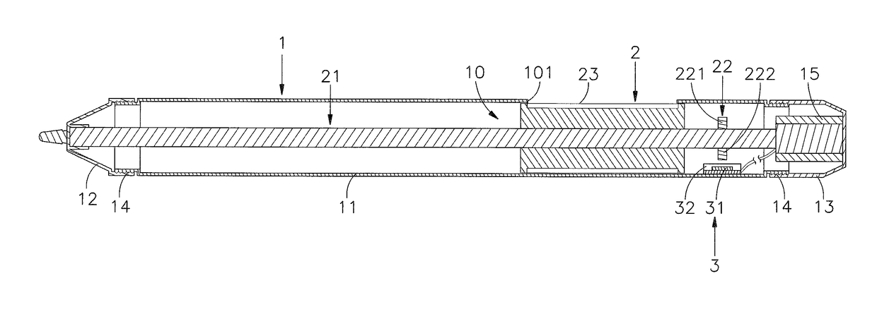
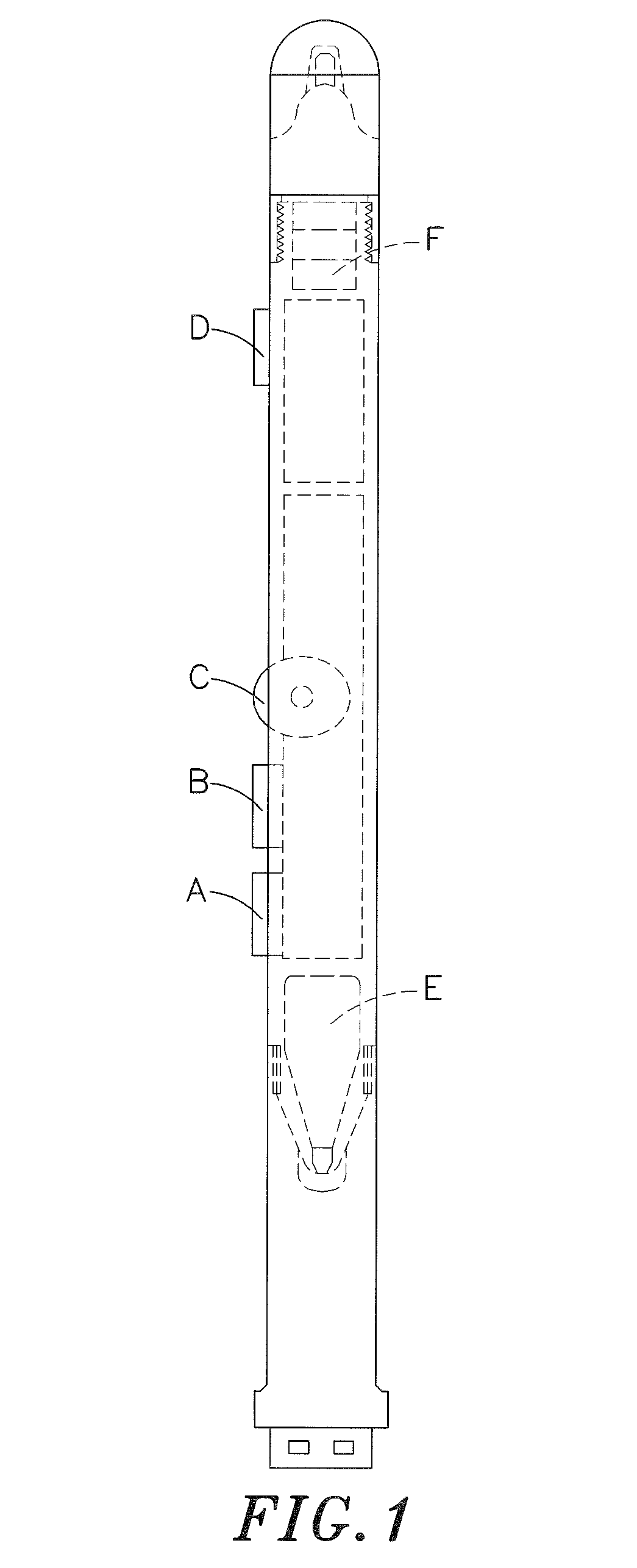
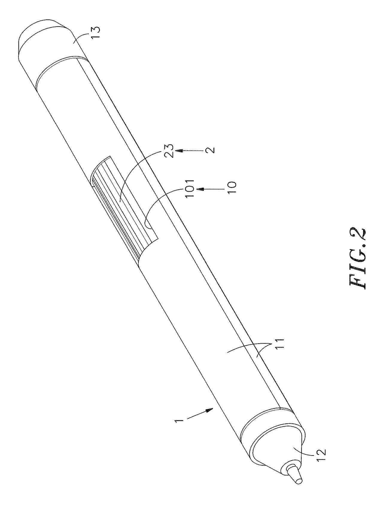
The present patent relates to a stylus for controlling electronic devices. The stylus has a unique design that solves the problem of large stylus size due to excessive components inside the stylus. The stylus has a pen holder with a hollow space, a wheel assembled inside the hose space, and a magnetic induction device on the inner wall of the hose space. The magnetic induction device can sense a variation of angular momentum or angular velocity of the magnetic field lines, and the data is converted into the movement per unit time of the wheel. The wheel is in direct contact with the magnetic component, and it has a non-slip touch surface for easy rotation. The stylus is designed for intuitive and easy operation, and it provides the user with better control over the electronic device.

Problems solved by technology

However, the user's finger may touch a larger area on the screen of the electronic device, so the user usually slides too many pages accidentally during the slide operation and touch operation, and it is not easy for the user to browse or change page precisely by using the finger touch control manner.
As a result, the user has to repeat up / down slide operations to reach the desired page, which results in inconvenience of operating the screen of the electronic device.
However, adding more control components makes the structural relationship between the components inside the stylus complex, and it causes the increasing size of the intelligent stylus.
In recent years, the size and the diameter of the intelligent stylus of the electronic device are larger than that of a normal pen, so it is not easy for the user to hold the intelligent stylus for operation.
When the pen body is designed to have more functions, the size of the pen body becomes larger and the user is not easy to hold the pen body.
However, compared with thumb, the index finger of the user's dominant hand is disadvantageous in rotating the wheel.

Method used


Image

  • Stylus with magnetic induction wheel
  • Stylus with magnetic induction wheel
  • Stylus with magnetic induction wheel

Examples


Embodiment Construction

[0029]The following embodiments of the present disclosure are herein described in detail with reference to the accompanying drawings. These drawings show specific examples of the embodiments of the present disclosure. It is to be understood that these embodiments are exemplary implementations and are not to be construed as limiting the scope of the present disclosure in any way. Further modifications to the disclosed embodiments, as well as other embodiments, are also included within the scope of the appended claims. These embodiments are provided so that this disclosure is thorough and complete, and fully conveys the inventive concept to those skilled in the art. Regarding the drawings, the relative proportions and ratios of components in the drawings may be exaggerated or diminished in size for the sake of clarity and convenience. Such arbitrary proportions are only illustrative and not limiting in any way. The same reference numbers are used in the drawings and description to ref...


PUM


Abstract

The present disclosure illustrates a stylus with magnetic induction wheel. In the stylus, a pen holder includes a stylus head and a pen cap, and the pen holder is defined with a hollow accommodation space having a hole. A wheel is assembled inside the accommodation space and aligned with the hole, and a central axis is protruded on and extended from two opposite sides of the wheel to abut with the stylus head and the pen cap. A magnetic component is disposed on the central axis, and a magnetic induction device is disposed in the accommodation space to sense a variation of angular momentum or angular velocity of the magnetic field lines of the S and N magnetic poles of the magnetic component. As a result, the user can use the stylus to control an electronic device more easily.

Description

[0001]This application claims the priority benefit of Taiwan patent application numbers 106102949 and 107101889, filed respectively on Jan. 25, 2017 and Jan. 18, 2018.BACKGROUND OF THE INVENTION1. Field of the Invention[0002]The present disclosure relates to a stylus with a magnetic induction wheel. More particularly, the present disclosure relates to a stylus having a wheel, and the wheel can be operated to control a page browse operation of a screen of a preset electronic device;[0003]furthermore, the wheel and a magnetic induction device is assembled inside an accommodation space in a pen holder, and magnetic induction coupling can be formed between two sensing points of the magnetic induction device and the magnetic component on a central axis of the wheel, thereby achieving the purpose of using a stylus head at a side of the pen holder to control the preset electronic device.2. Description of the Related Art[0004]With continuous progress of the electronic technology, the portab...

Claims


Application Information

Patent Timeline
Patent Type & Authority Applications(United States)
IPC IPC(8): G06F3/0354
CPCG06F3/03545G06F3/0362G06F3/0383
Inventor CHIANG, CHIU-LINCHIEN, MING-HUNGLIN, CHANG-CHING
Owner HOLY STONE ENTERPRISE
Features
  • R&D
  • Intellectual Property
  • Life Sciences
  • Materials
  • Tech Scout
  • Unparalleled Data Quality
  • Higher Quality Content
  • 60% Fewer Hallucinations
Learn More