Collapsible log splitting assembly with safety perimeter

a safety perimeter and log splitting technology, applied in wood splitting, metal working equipment, manufacturing tools, etc., can solve the problems of large logs being loaded onto log splitters, laborious, back breaking, etc., and achieve the effect of saving manpower and time, reducing labor intensity, and reducing labor intensity

Inactive Publication Date: 2018-08-16
ZAKE IP HLDG LLC
View PDF4 Cites 15 Cited by
  • Summary
  • Abstract
  • Description
  • Claims
  • Application Information

AI Technical Summary

Benefits of technology

[0007]Illustrative embodiments of the disclosure are generally directed to a collapsible log splitting assembly with safety perimeter. The collapsible log splitting assembly serves to split a log, kindling, or general workpiece through use of a unique blade having a parabolic-shaped cross section, and a blade housing having a plurality of ridges that work to further separate the split log. The assembly further comprises a safety perimeter barrier that forms around a predetermined periphery of the assembly. The perimeter barrier serves to: retain the log in an upright position, inhibit the log from being forcefully displaced from the circumferential area of the assembly while splitting, and protect an operator from inadvertent contact with the blade. Additionally, the assembly has a generally upright disposition when in an operational position, which is pivotally collapsible into a planar, collapsed position when not in use.

Problems solved by technology

It is known in the art that hand splitting of logs is a tedious, back breaking job.
It is also costly and time consuming to any business which finds it necessary to split logs as a step or part of a manufacturing operation, or in the production of an end item, such as firewood.
Further, hand loading of a log onto a log splitter can be a difficult task for larger log.
One problem from the current power devices is the fact that the log being split can become stuck on the wedge.
When the log is stuck on the wedge, a substantial amount of hand work can be required to loosen the log.
Also some of the prior art devices have semi-circular bases which cause excess log splitting forces when logs wedge against the semi-circular log holder.
The problem with these splitting mechanisms is that they do not provide a blade that is dimensioned to optimize cutting efficiency.
There are also safety concerns, since the operator is fully exposed to the blade and flying debris from the log as it is being split.

Method used


Image

  • Collapsible log splitting assembly with safety perimeter
  • Collapsible log splitting assembly with safety perimeter
  • Collapsible log splitting assembly with safety perimeter

Examples


Embodiment Construction

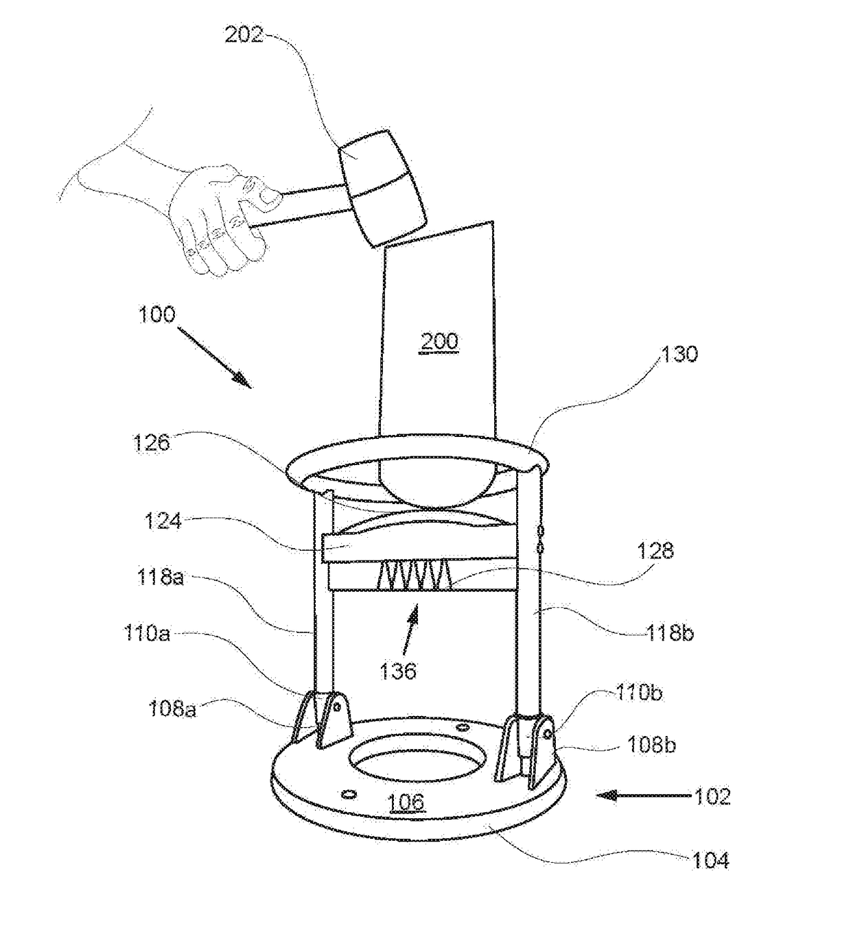
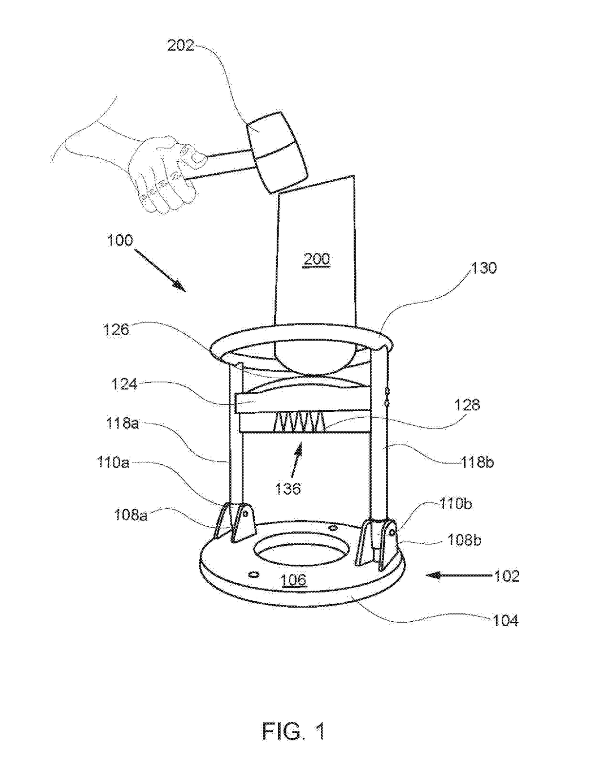
[0036]The following detailed description is merely exemplary in nature and is not intended to limit the described embodiments or the application and uses of the described embodiments. As used herein, the word “exemplary” or “illustrative” means “serving as an example, instance, or illustration.” Any implementation described herein as “exemplary” or “illustrative” is not necessarily to be construed as preferred or advantageous over other implementations. All of the implementations described below are exemplary implementations provided to enable persons skilled in the art to make or use the embodiments of the disclosure and are not intended to limit the scope of the disclosure, which is defined by the claims. For purposes of description herein, the terms “upper,”“lower,”“left,”“rear,”“right,”“front,”“vertical,”“horizontal,” and derivatives thereof shall relate to the invention as oriented in FIG. 1. Furthermore, there is no intention to be bound by any expressed or implied theory pres...


PUM


Abstract

A collapsible log splitting assembly with safety perimeter splits a log with a parabolic-shaped blade, a blade housing having a plurality of ridges for separating the split log further, and a perimeter barrier for retaining the log upright while splitting, and protecting an operator from contact with blade. The assembly has an upright disposition that is pivotally collapsible into a planar configuration when not in use. The assembly has a base that is for support on a surface. The base includes a pair of brackets. A pair of sleeves pivotally join with the brackets, pivoting about the brackets. A pair of shafts slide within sleeves, sliding between operational and collapsed positions. A cutting apparatus comprises a blade housing that houses a parabolic blade, and extends between the shafts. Ridges along the base housing separate the log into smaller components. The perimeter barrier detachably attaches to top end of the shafts.

Description

FIELD OF THE INVENTION[0001]The present invention relates generally to a collapsible log splitting assembly with safety perimeter. More so, the present invention relates to a collapsible log splitting assembly that splits a log with a blade having a parabolic-shaped cross section, and a blade housing having ridges that separate and organize portions of the split log; and that further includes a safety perimeter for maintaining the log within a predetermined circumferential area of the assembly while splitting, and for preventing inadvertent contact with the blade; and further the assembly pivotally assembles into an operational position, and collapses into a generally flat configuration for stowage.BACKGROUND OF THE INVENTION[0002]The following background information may present examples of specific aspects of the prior art (e.g., without limitation, approaches, facts, or common wisdom) that, while expected to be helpful to further educate the reader as to additional aspects of the ...

Claims


Application Information

Patent Timeline
Patent Type & Authority Applications(United States)
IPC IPC(8): B27L7/06
CPCB27L7/06B27G21/00B26D1/02B26D7/22B26D3/30
Inventor ZHU, JIANQINGMCGREW, BENJAMIN PAUL
Owner ZAKE IP HLDG LLC
Why Eureka
Try Eureka