Lamp device

Active Publication Date: 2018-08-16
KOITO MFG CO LTD
View PDF2 Cites 7 Cited by
  • Summary
  • Abstract
  • Description
  • Claims
  • Application Information

AI Technical Summary

Problems solved by technology

However, since the sensor for acquiring information outside the vehicle based on invisible light generally has a relatively large volume, the sensor tends to be subject to layout restriction in the lamp room.
Therefore, compared with a conventional lamp dev

Method used


Image

  • Lamp device
  • Lamp device
  • Lamp device

Examples


Embodiment Construction

[0027]Embodiments will be described in detail below with reference to the drawings. In each drawing used in the following description, the scale is appropriately changed in order to make each member in a recognizable size.

[0028]In the drawings, Arrow F indicates a forward direction of the illustrated structure. Arrow B indicates a backward direction of the illustrated structure. Arrow U indicates an upward direction of the illustrated structure. Arrow D indicates a downward direction of the illustrated structure. Arrow L indicates a left direction of the illustrated structure. Arrow R indicates a right direction of the illustrated structure. The “left” and “right” used in the following description indicate the left and right directions viewed from a driver's seat.

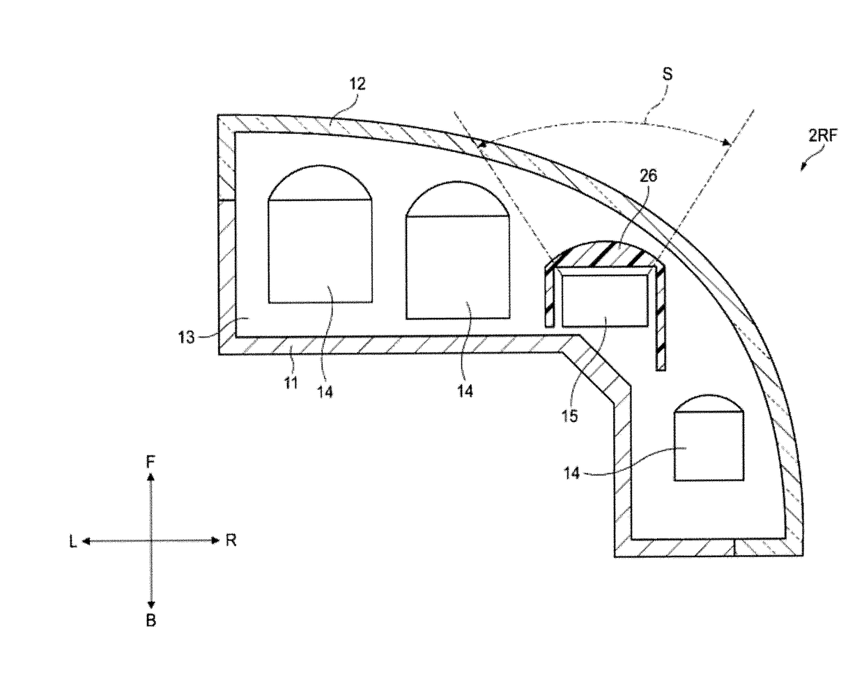
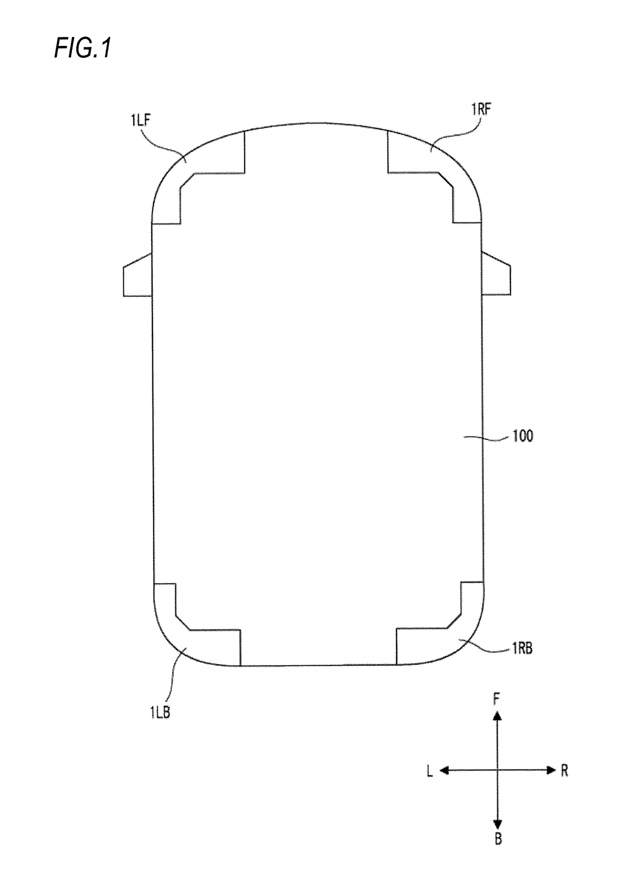
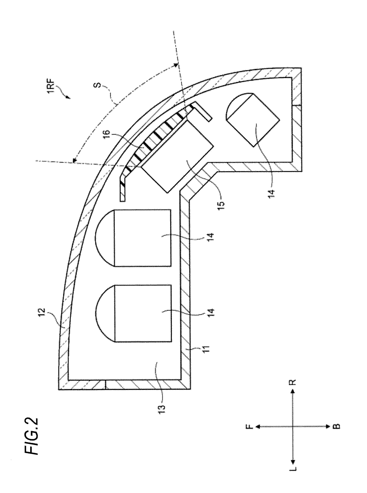
[0029]As shown in FIG. 1, a left-front lamp device 1LF according to a first embodiment is mounted on a left-front corner portion of a vehicle 100. A right-front lamp device 1RF according to the first embodiment is mounted o...


PUM


Abstract

A lamp device mounted on a vehicle includes a housing, a first translucent member defining a housing space together with the housing, a lamp unit housed in the housing space and including a light source, a sensor housed in the housing space and configured to detect information outside the vehicle based on invisible light, and a second translucent member housed in the housing space and covering the sensor. The second translucent member has transmittance of visible light lower than that of the first translucent member.

Description

CROSS-REFERENCE TO RELATED APPLICATIONS[0001]The present application claims the benefit of priority of Japanese Patent Application No. 2017-023184, filed on Feb. 10, 2017, the content of which is incorporated herein by reference.TECHNICAL FIELD[0002]The present invention relates to a lamp device to be mounted on a vehicle.BACKGROUND ART[0003]In order to achieve driving support of a vehicle, it is necessary to mount on a vehicle body a sensor for acquiring information outside the vehicle. There has been known a Light Detection and Ranging (LiDAR) sensor as one example of such a sensor (for example, see JP-A-2010-185769). The LiDAR sensor is a device for emitting invisible light and acquiring information on a distance to an object and an attribute of the object based on a reflected light.[0004]From a viewpoint of efficiently acquiring information on surroundings of the vehicle and from a viewpoint of design, it is desired to dispose the sensor in a lamp room of the lamp device provide...

Claims


Application Information

Patent Timeline
IPC IPC(8): B60Q1/00F21S45/10G01S13/93G01S15/93G01S17/93G01S13/931G01S15/931G01S17/931
CPCB60Q1/0023F21S45/10G01S13/931G01S15/931G01S17/936G01S2013/9396G01S2015/937B60Q1/04G01S17/931F21S41/285F21S41/50G01S7/4813G01S2013/93277
Inventor HARA, HIROAKIOSADA, KAZUHITOHORIKAWA, NOBUYUKI
Owner KOITO MFG CO LTD
Why Eureka
Try Eureka