Fuel injection control device

a control device and fuel injection technology, applied in the direction of fuel injection control, electric control, machines/engines, etc., can solve the problems of fuel easily adhering to the wall surface, excessive or insufficient amount of fuel that contributes to the actual combustion, and easy failure of fuel vaporization

Active Publication Date: 2018-08-16
TOYOTA JIDOSHA KK
View PDF4 Cites 10 Cited by
  • Summary
  • Abstract
  • Description
  • Claims
  • Application Information

AI Technical Summary

Benefits of technology

[0004]An objective of the present invention is to provide a fuel injection control device capable of appropriately performing correction to increase a fuel injection amount during the cold startup of an internal combustion engine the injection mode of which is switched between direct injection and port injection.

Problems solved by technology

During the cold time of an internal combustion engine, a failure in fuel vaporization easily occurs and fuel easily adheres to a wall surface.
For this reason, if both the fuel injection amount in direct injection and the fuel injection amount in port injection are increased in the same manner during the cold time, the amount of fuel that contributes to the actual combustion may be excessive or insufficient.

Method used


Image

  • Fuel injection control device
  • Fuel injection control device
  • Fuel injection control device

Examples


Embodiment Construction

[0018]A fuel injection control device 30 according to one embodiment of the present invention will now be described with reference to FIGS. 1 to 10.

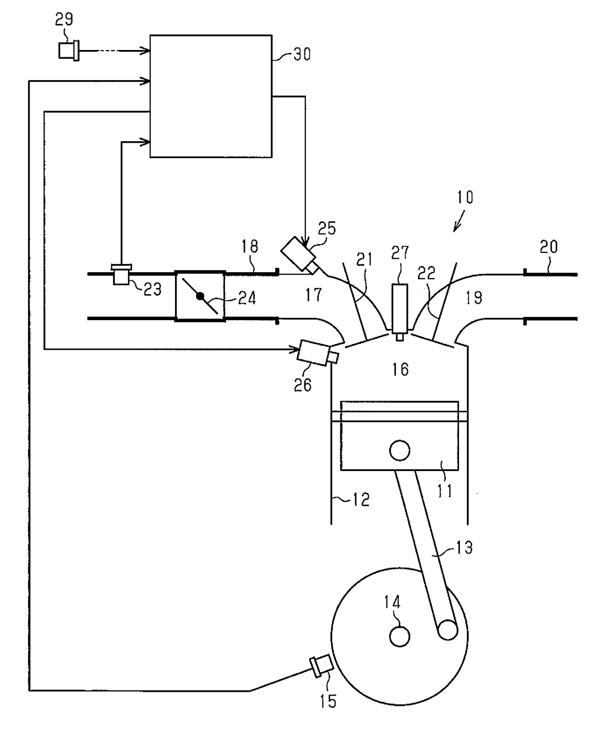
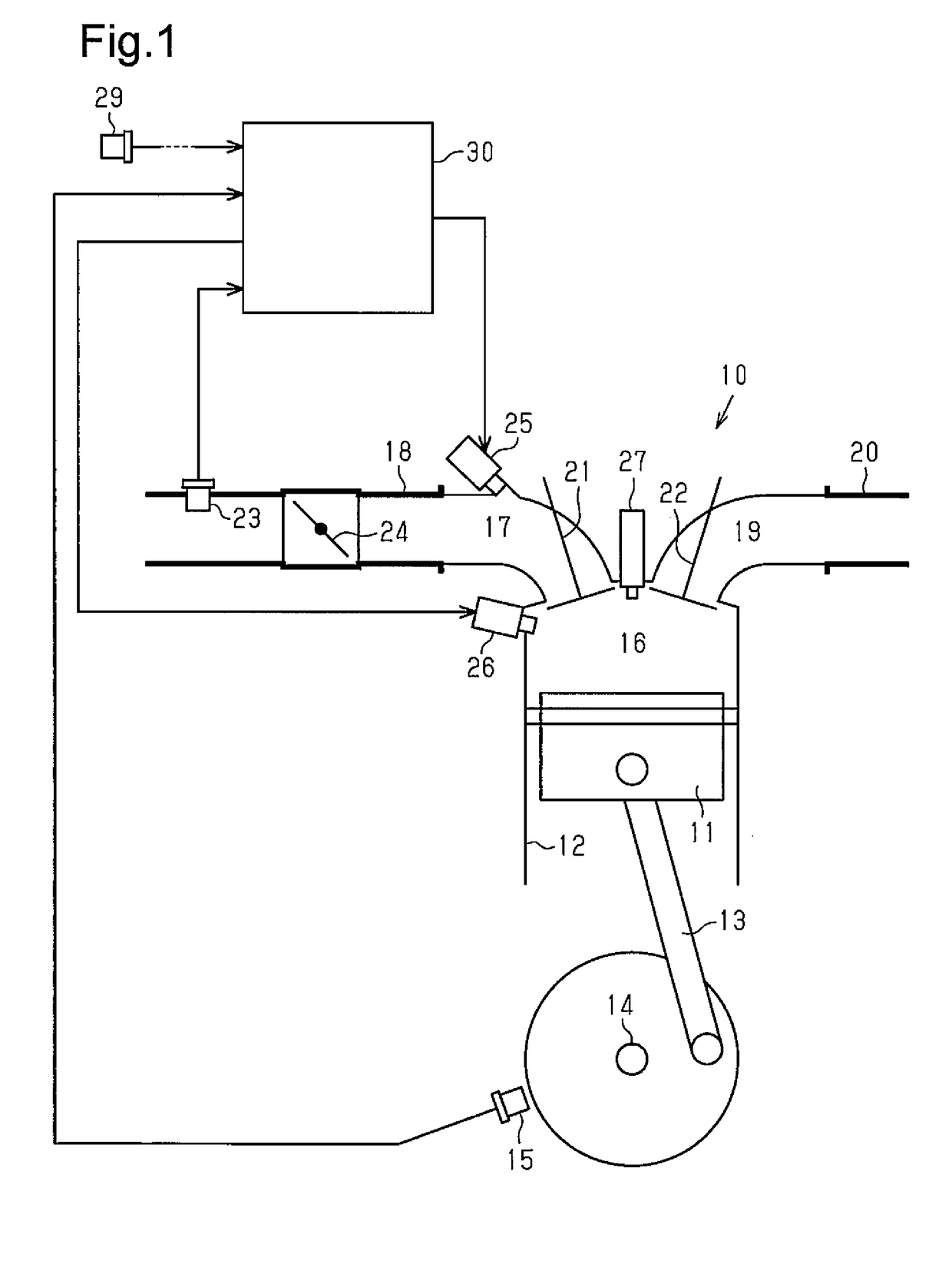
[0019]First, a description is given of the configuration of an internal combustion engine 10 to which the fuel injection control device 30 of the present embodiment is applied with reference to FIG. 1.

[0020]The internal combustion engine 10 includes a cylinder 12 that accommodates a piston 11 in a reciprocatable manner. The piston 11 is connected to a crankshaft 14 via a connecting rod 13. The connection structure therebetween functions as a crank mechanism of converting reciprocating motion of the piston 11 to rotating motion of the crankshaft 14. Further, a crank angle sensor 15 that outputs a pulse signal (a crank angle signal CR) according to rotation of the crankshaft 14 is provided near the crankshaft 14 in the internal combustion engine 10.

[0021]Inside the cylinder 12, a combustion chamber 16 is defined by the piston 11. An intake...


PUM


Abstract

A cold-time fuel increasing section calculates, as increase correction values for a required injection amount, an increase-after-startup correction value, which attenuates with an increment of the number of times of combustion carried out after startup of the internal combustion engine, and a basic warmup increase correction value, which attenuates with an increase in a temperature of coolant in the internal combustion engine. The cold-time fuel increasing section calculates the increase correction values such that the increase-after-startup correction value when the port injection mode is selected is greater than the increase-after-startup correction value when the single direct injection mode is selected, and that the basic warmup increase correction value when the port injection mode is selected is less than the basic warmup increase correction value when the single direct injection mode is selected.

Description

BACKGROUND OF THE INVENTION[0001]The present invention relates to a fuel injection control device configured to switch an injection mode between direct injection and port injection.[0002]During the cold time of an internal combustion engine, a failure in fuel vaporization easily occurs and fuel easily adheres to a wall surface. Consequently, some of injected fuel does not make any contribution to combustion. For this reason, it is common to increase a fuel injection amount during such cold time of an internal combustion engine. Meanwhile, as described in Japanese Laid-Open Patent Publication No. 2012-117472, an internal combustion engine has been known that is provided with two different types of fuel injection valves including a port injection valve, which injects fuel into an intake port, and a direct injection valve, which injects fuel into a combustion chamber. In the internal combustion engine, the injection mode is switched such that the injection ratio of the direct injection...

Claims


Application Information

Patent Timeline
Patent Type & Authority Applications(United States)
IPC IPC(8): F02D41/30F02D41/06F02D41/04
CPCF02D41/3094F02D41/064F02D41/068F02D41/047F02D2200/021F02D41/061
Inventor KITAZUME, AKINORIIDOGAWA, MASANAOMIZUNO, HIROYUKI
Owner TOYOTA JIDOSHA KK
Why Eureka
Try Eureka