
Decoupling capacitor

a decoupling capacitor and capacitor technology, applied in the direction of capacitor testing, instruments, electrical equipment, etc., can solve the problem that the sites in which the decoupling capacitors are located run the risk of being targeted most specifically by pirates

Active Publication Date: 2018-08-16
STMICROELECTRONICS (CROLLES 2) SAS
View PDF0 Cites 2 Cited by
  • Summary
  • Abstract
  • Description
  • Claims
  • Application Information

AI Technical Summary

Benefits of technology

This patent describes a type of capacitor that is placed between two conductive strips in a semiconductor device. The capacitor is made up of two cells that are isolated from each other by a trench. The cells are formed by a first trench isolation and a second trench isolation that is perpendicular to the first. This design helps to reduce interference between the cells and improves the performance of the capacitor. The patent also includes an integrated circuit that contains this new decoupling capacitor.

Problems solved by technology

The sites in which the decoupling capacitors are located therefore run the risk of most particularly being targeted by pirates.

Method used


Image

  • Decoupling capacitor
  • Decoupling capacitor
  • Decoupling capacitor

Examples


Embodiment Construction

[0021]Elements that are the same have been referenced by the same references in the various figures and, in addition, the various figures have not been drawn to scale. For the sake of clarity, only those elements that are useful to the comprehension of the described embodiments have been shown and are detailed.

[0022]In the following description, when reference is made to qualifiers of position, such as the terms “front,”“back,”“under.”“horizontal,”“vertical,” etc., reference is being made to the position of the elements in question in the figures. Unless otherwise specified, the expression “approximately” must be interpreted as meaning to within 10% and preferably to within 5%.

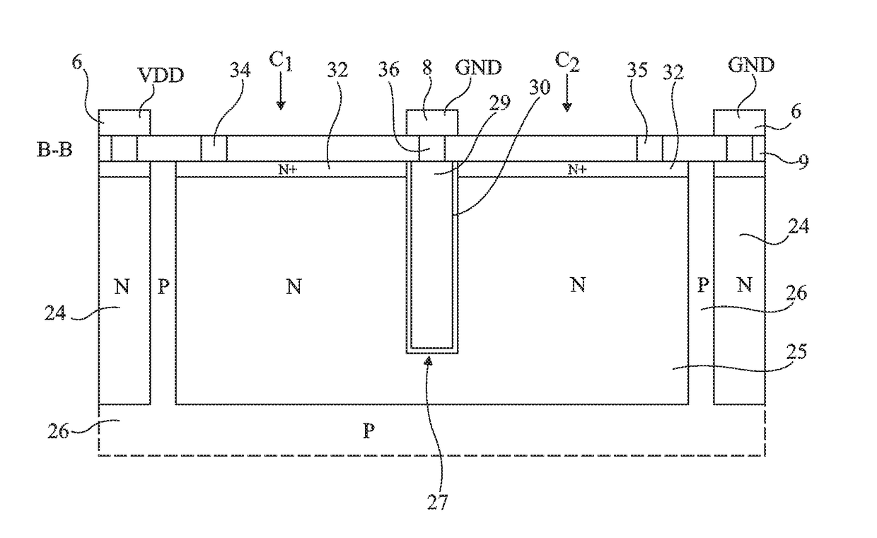
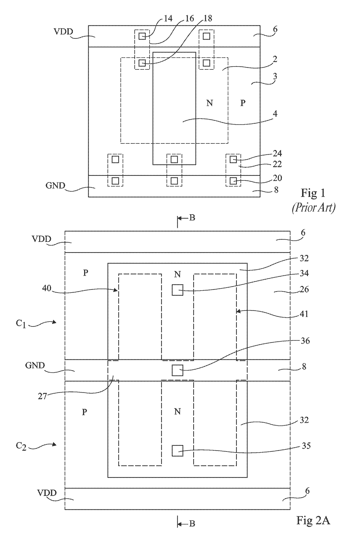
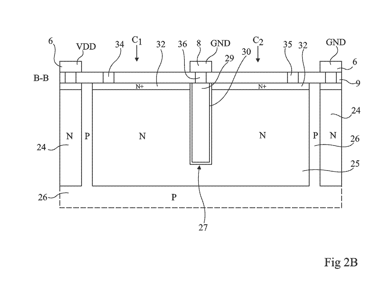
[0023]FIGS. 2A and 2B are a top view and a cross-sectional view along the line B-B of FIG. 2A, showing one embodiment of two capacitor cells, these capacitors being protected from back-side attacks. The capacitors are here, by way of example, capacitors based on trench isolations.

[0024]As was described above, ...


PUM


Abstract

A decoupling capacitor includes: two capacitor cells sharing the same well; a first trench isolation passing through the well between the two cells without reaching the bottom of the well; and a contact with the well formed in each cell.

Description

BACKGROUNDTechnical Field[0001]The present application relates to integrated electronic circuits, and more particularly to an integrated circuit equipped with a back-side device protecting the circuit.Description of the Related Art[0002]Integrated circuits are sometimes subjected to attacks the aim of which is to determine the structure of the circuit, to modify the operation thereof or to extract confidential information therefrom. An attack may be carried out from the back side of a circuit equipped on its front side with components such as capacitors, diodes or transistors, coated with conductive tracks. During the attack, a section of the back side is first etched, approximately down to level with the wells in which the components are formed. A smaller aperture, for example of 2 μm×2 μm size, is formed in this section of the back side, approximately down to level with active zones and shallow trench isolations (STIs). In this aperture, cavities are produced, for example by ion b...

Claims


Application Information

Patent Timeline
IPC IPC(8): H01L23/00H01L23/528H01L23/522G01R31/02
CPCH01L23/573H01L23/5286H01L23/5223G01R31/028H01L23/576H01L23/642H01L25/16H01L29/945H01L23/58G01R31/64
Inventor LISART, MATHIEUFROMENT, BENOIT
Owner STMICROELECTRONICS (CROLLES 2) SAS
Learn More