Eureka AIR delivers breakthrough ideas for toughest innovation challenges, trusted by R&D personnel around the world.

Drive force control system

Active Publication Date: 2018-08-23
TOYOTA JIDOSHA KK
View PDF0 Cites 3 Cited by
  • Summary
  • Abstract
  • Description
  • Claims
  • Application Information

AI Technical Summary

Benefits of technology

The present patent text describes a system for improving the turning performance of a vehicle by adjusting the torque of the right and left pairs of wheels based on the difference between the target yaw rate and the actual yaw rate. When the steering angle exceeds a predetermined angle, correction torques are calculated to adjust the torque of the wheels to achieve the target yaw rate. The system allows for a greater yaw rate when the steering wheel is turned to the maximum rotational angle, leading to improved vehicle performance.

Problems solved by technology

However, in the conventional vehicles, a turning angle of the steering wheel is mechanically limited.
That is, if the target yaw rate is calculated based on a turning angle of the steering wheel, a yaw rate greater than an upper limit angle of the steering wheel cannot be achieved.

Method used


Image

  • Drive force control system
  • Drive force control system
  • Drive force control system

Examples


Embodiment Construction

)

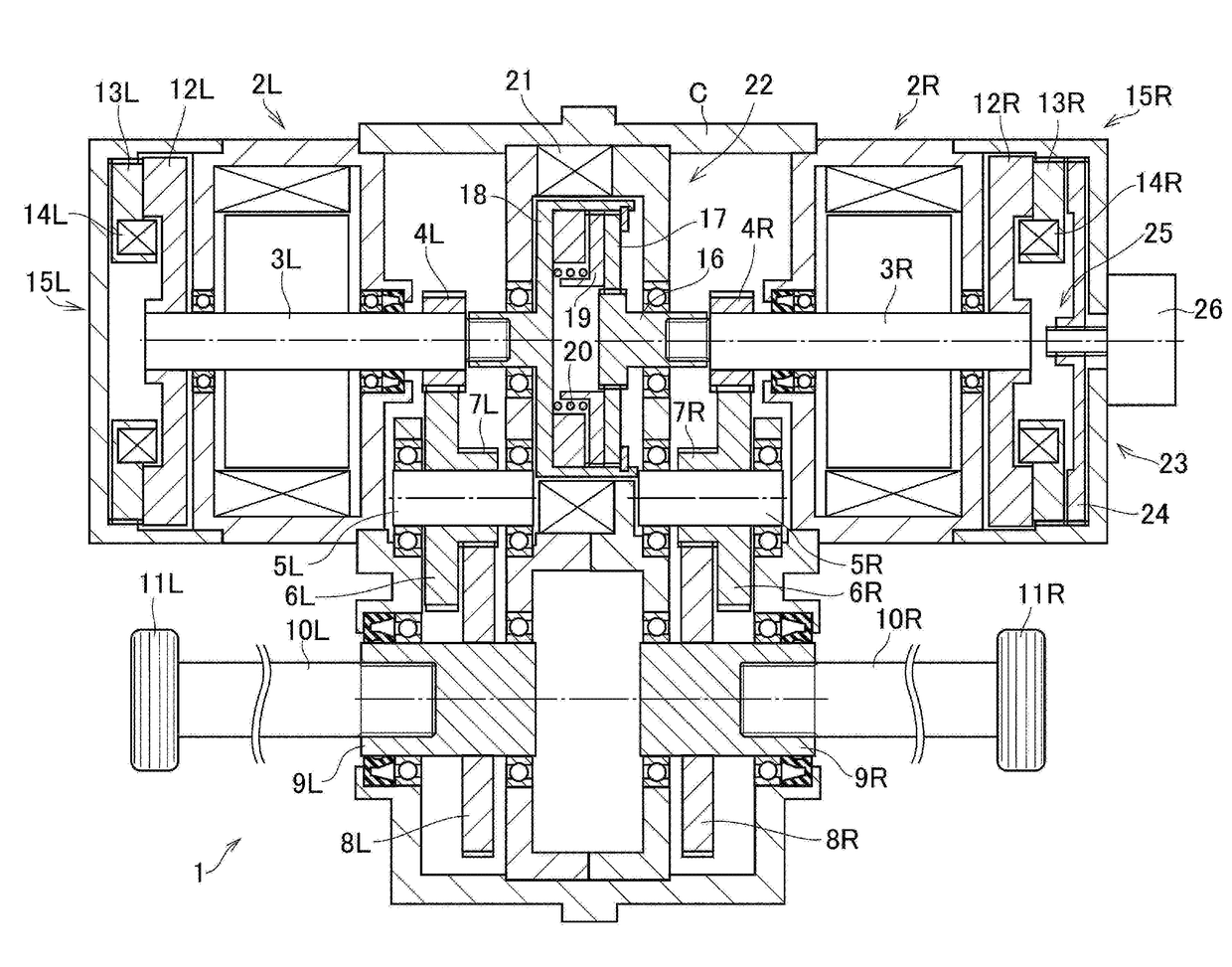
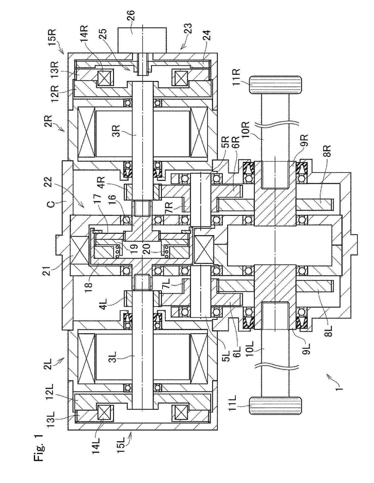
[0023]Embodiment of the present disclosure will now be explained with reference to the accompanying drawings. Turning now to FIG. 1, there is shown one example of a structure of a drive unit to which the drive force control system according to the present disclosure is applied. As can be seen from FIG. 1, a structure of the drive unit 1 is substantially symmetrical across a width center of the vehicle. In the following explanation, only a configuration on the right half in the figure will be explained, and an explanation for the left half will be omitted except for a configuration different from that of the right half. In FIG. 1, accordingly, the reference letter “R” designates members arranged in the right half of the drive unit 1, and the reference letters “L” designates members arranged in the left half of the drive unit 1. In the flowing explanation, the members in the right half of the drive unit 1 will be called the “first member”, and the members in the left half of the driv...


PUM


Abstract

A drive force control system to increase a yaw rate greater than the yaw rate achieved by rotating a steering wheel to a maximum angle. A target yaw rate is calculated based on a steering angle of the steering wheel. A first predetermined torque and a second predetermined torque are calculated based on a difference between the target yaw rate and an actual yaw rate. When the steering angle of the steering wheel exceeds a first predetermined angle, a first correction torque to correct the first predetermined torque and a second correction torque to correct the second predetermined torque are calculated in accordance with the steering torque.

Description

CROSS REFERENCE TO RELATED APPLICATION[0001]The present invention claims the benefit of Japanese Patent Application No. 2017-030916 filed on Feb. 22, 2017 with the Japanese Patent Office, the disclosures of which are incorporated herein by reference in its entirety.BACKGROUNDField of the Invention[0002]Embodiments of the present disclosure relate to the art of a drive force control system for vehicles configured to generate a yaw moment in accordance with an operation of a steering wheel.Discussion of the Related Art[0003]JP-A-2005-151623 discloses a behavior control device for electric vehicles that controls torques applied to each drive wheel. According to the teachings of JP-A-2005-151623, a target turning amount such as a yaw rate, and a basic value of target slip angle between a travelling direction of the vehicle and an orientation of the vehicle are calculated based on a turning angle of a steering wheel. Then, a difference between drive forces of the right and left drive whe...

Claims


Application Information

Patent Timeline
IPC IPC(8): B62D9/00B62D6/10B62D5/04B62D6/00
CPCB62D9/002B62D6/10B62D5/0463B62D6/003B62D5/0412B60W2540/18B60W2720/14B60W2720/406B60W30/045B60W30/00
Inventor NASU, TAKANOBUISONO, HIROSHISASAKI, HIDEKAZU
Owner TOYOTA JIDOSHA KK
Why Eureka
Eureka Blog
Learn More