Process of using a hydroelectric generator in a water course to generate electricity

Inactive Publication Date: 2018-08-23
CINQUE GLEDIS
View PDF2 Cites 2 Cited by
  • Summary
  • Abstract
  • Description
  • Claims
  • Application Information

AI Technical Summary

Benefits of technology

[0009]It is an object of the present invention to provide a hydroelectric generator wit

Problems solved by technology

This solution ensures that a larger rotor surface contacting the fluid, but is very complex to design, install and maintain.
In fact, there are portions of the machine which have to work always submerged, that is in an adverse environment.
Moreover, such a machine largely interferes with the water course.
Being these machines expensive and not very adaptable, they cannot be used in low-speed water courses.
Moreover, a machine with semi-submerged rotor of large size also involves a hi

Method used


Image

  • Process of using a hydroelectric generator in a water course to generate electricity
  • Process of using a hydroelectric generator in a water course to generate electricity
  • Process of using a hydroelectric generator in a water course to generate electricity

Examples


Example

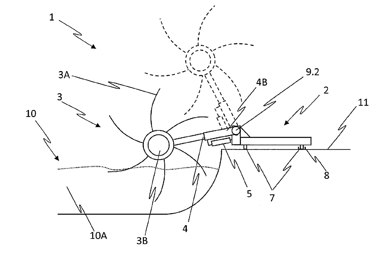
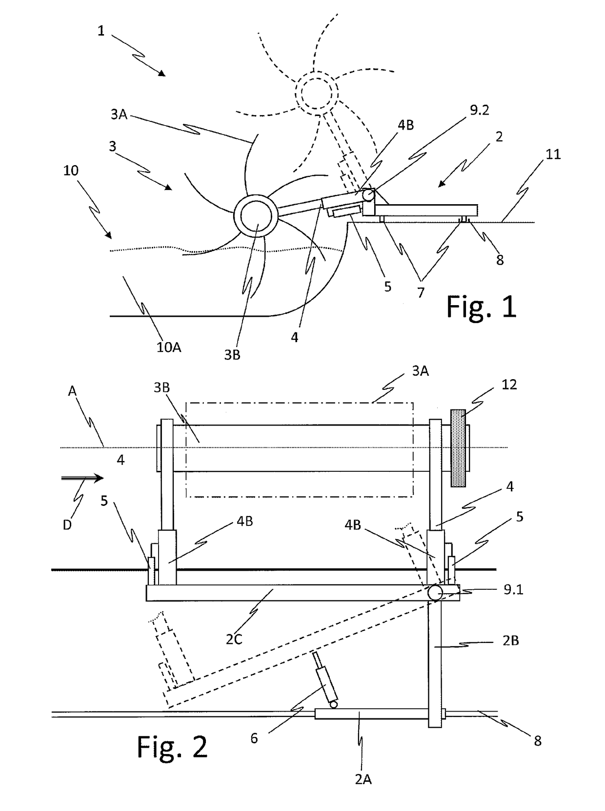
[0040]Referring to FIGS. 1 and 2, a hydroelectric generator 1, hereinafter generator 1, consists of a fixed platform 2, for constraining the generator 1 to the ground 11 and rotor means 3 for converting the kinetic energy of a fluid 10A, hereinafter water 10A, of a water course 10. The platform 2 is a structure adapted to stably anchor the machine to the ground and, at the same time, to support the rotor means 3 and to counteract the forces acting on the rotor means 3 themselves.

[0041]In the embodiment shown in figures, the structure consists of a set of beam elements 2A, 2B e 2C even if, as clear, different structure shapes are possible. The generator 1 comprises means 4, 5, 6 for adjusting the position of the rotor means 3, constrained to the fixed platform 2. The adjusting means 4, 5, 6 provide the rotor means 3 with at least one degree of freedom. In particular, the adjusting means 4, 5, 6 allow to change at least the orientation of the axis A of the rotor means 3 with respect t...


PUM


Abstract

Disclosed is a process of using a hydroelectric generator adapted to be installed in a water course, having a semi-submerged rotor, including a fixed platform, a rotor means for the conversion of kinetic energy of a fluid in electric energy, having adjusting means to adjust the position of the rotor means. The adjusting means to adjust the position of the rotor means is constrained to the fixed platform and moves, in a controlled way, the rotor means with respect to the fixed platform with at least one degree of freedom, to change at least the orientation of the axis (A) of the rotor with respect to the main flow direction (D) of the water.

Description

CROSS-REFERENCE TO RELATED APPLICATIONS[0001]This application is a Divisional of U.S. application Ser. No. 14 / 764,712, filed Jul. 30, 2015, which in turn is a 371 of PCT / IB2014 / 059043, filed Feb. 17, 2014, which claims the benefit of Italian Patent Application No. MI2013A000217, filed Feb. 18, 2013. The contents of each of which are incorporated herein by reference.FIELD OF THE INVENTION[0002]The present invention relates to the use of a hydroelectric generator adapted to be installed in a water course, having a semi-submerged rotor. Semi-submerged rotor means that the rotor blades are only in partly submerged in the water course.BACKGROUND OF THE INVENTION[0003]In particular, the present invention relates to a hydroelectric generator adapted to be installed in rivers wherein the water flows at a low speed.[0004]As known, a hydraulic generator is a machine converting the kinetic energy of a fluid into electric energy, usually by means of an alternator driven by a rotor which is rota...

Claims


Application Information

Patent Timeline
IPC IPC(8): F03B17/06
CPCF05B2240/91Y02E10/28F03B17/061Y02E10/20
Inventor CINQUE, GLEDIS
Owner CINQUE GLEDIS
Why Eureka
Try Eureka