Optical lens assembly and electronic apparatus including the same

a technology of optical lens and electronic equipment, applied in the direction of optics, mountings, instruments, etc., can solve the problems of reducing the performance degradation of optical lenses, reducing the difficulty of aberration control, and reducing the difficulty of temperature changes, so as to achieve the effect of minimizing the performance degradation

Active Publication Date: 2018-08-23
SAMSUNG ELECTRONICS CO LTD
View PDF0 Cites 40 Cited by
  • Summary
  • Abstract
  • Description
  • Claims
  • Application Information

AI Technical Summary

Benefits of technology

[0005]As the use of imaging devices in portable apparatuses has increased, there is an increasing demand for miniaturization of such imaging devices. However, in the case of a wide-angle lens system, it is difficult to perform aberration control while also miniaturizing the lens system. Also, since wide-angle lens systems are sensitive to temperature changes, minimizing performance degradation due to temperature changes is also required.

Problems solved by technology

However, in the case of a wide-angle lens system, it is difficult to perform aberration control while also miniaturizing the lens system.
Also, since wide-angle lens systems are sensitive to temperature changes, minimizing performance degradation due to temperature changes is also required.

Method used


Image

  • Optical lens assembly and electronic apparatus including the same
  • Optical lens assembly and electronic apparatus including the same
  • Optical lens assembly and electronic apparatus including the same

Examples


first embodiment

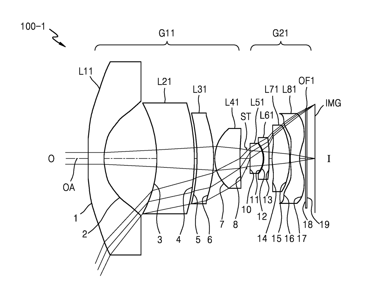
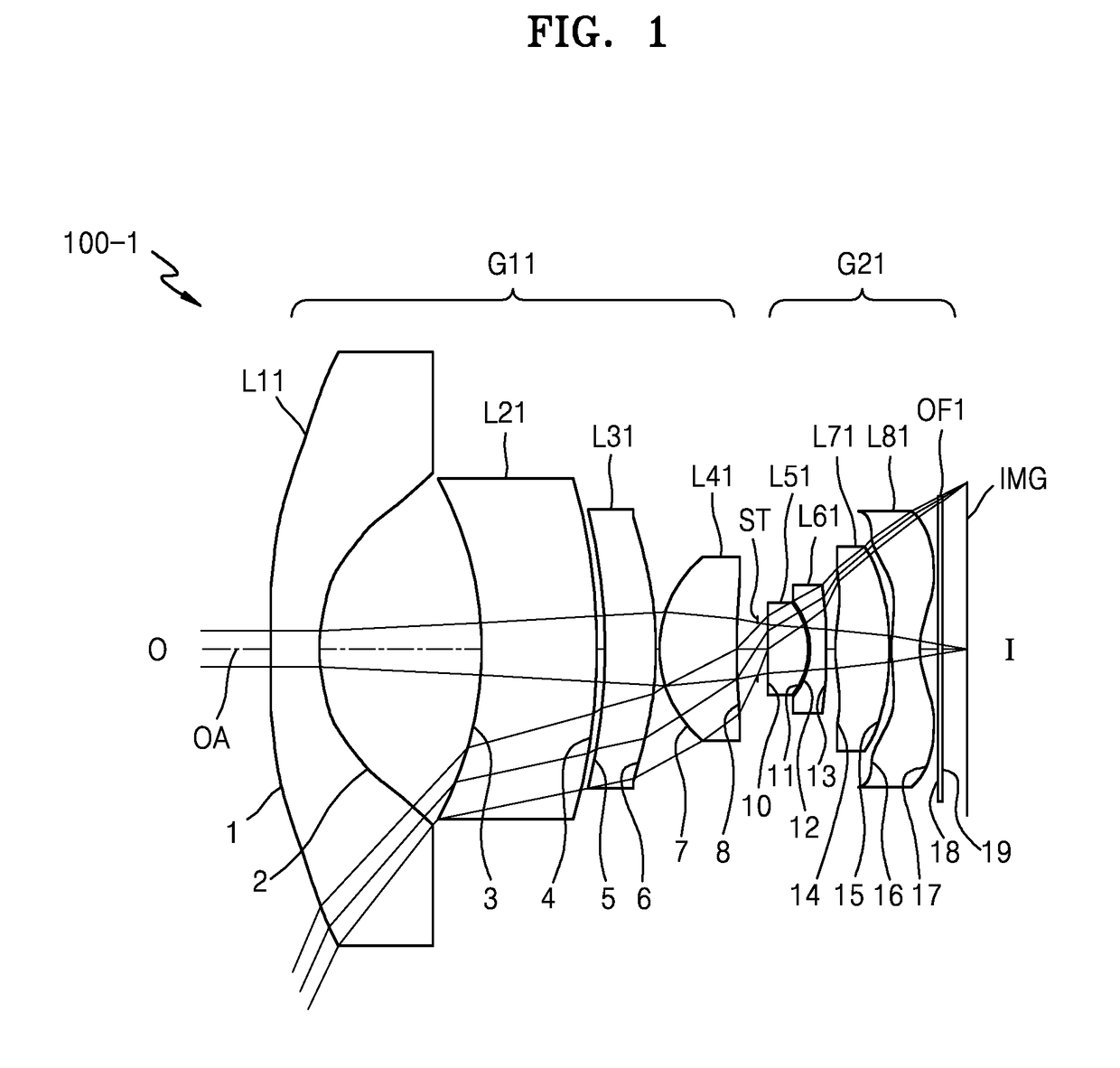
[0099]FIG. 1 illustrates an optical lens assembly according to a first embodiment. Table 1 shows, for example, design data of the first embodiment.

[0100]f: 2.19 mm Fno: 2.91 2w: 131.93°

TABLE 1Lens surfaceRDnndvdEFLobjinfinity 1*−169.3541.0531.544156.09−7.927 2*4.4353.531 3*−6.6852.4661.6503821.52−25.667 4*−12.7730.174 5*−12.1631.1021.6349323.8922.95 6*−6.8630.1 7*2.4891.6721.5891660.624.607 8*22.5420.442STinfinity0.24310*74.860.8671.544156.093.20911*−1.780.03212*−1.6030.3511.6503821.52−2.6613*−23.7380.20214*4.8141.1611.534855.713.71815*−3.1020.0516*4.0760.6081.534855.71−4.30517*1.3950.3818infinity0.111.516864.2infinity19infinity0.523IMGinfinity

[0101]Table 2 shows aspherical coefficients in the first embodiment.

TABLE 2Lens surface123456K(Conic)−50.0000−0.7526−0.0933−2.23495.1206−6.7171A(4th)4.9075E−036.2251E−032.0702E−042.5333E−043.1982E−042.6897E−04B(6th)−2.4337E−04 4.2033E−043.0640E−05−1.2369E−05 1.4825E−05−9.0331E−05 C(8th)5.8947E−06−5.0664E−05 0.0000E+000.0000E+000.0000E+008.5121...

second embodiment

[0103]FIG. 3 illustrates an optical lens assembly according to a second embodiment. Table 3 shows, for example, design data of the second embodiment.

[0104]f: 2.19 mm Fno: 2.90 2w: 131.81°

TABLE 3Lens surfaceRDnndvdEFLobjinfinityinfinity 1*5001.0531.5891660.62−7.466 2*4.3573.515 3*−6.7741.9641.6503821.52−12.682 4*−42.2220.156 5*−36.731.4221.6349323.8912.636 6*−6.6830.1 7*2.4861.6611.5891660.624.737 8*17.1440.471stoinfinity0.22310*23.5140.8771.544156.093.39611*−1.9790.02812*−1.8460.441.6503821.52−2.82213*375.5340.15614*5.0541.1291.534855.713.85215*−3.2070.0516*3.720.581.534855.71−4.59317*1.3990.3818infinity0.111.516864.2infinity19infinity0.574IMGinfinity

[0105]Table 4 shows aspherical coefficients in the second embodiment.

TABLE 4Lens surface123456K(Conic)−30.0000−0.6975−0.1285−1.539714.8436−5.7206A(4th)4.8786E−036.5766E−032.1624E−041.4030E−042.5440E−043.2255E−04B(6th)−2.4517E−04 3.6511E−042.2605E−05−5.2969E−06 −3.0704E−06 −7.8026E−05 C(8th)5.9000E−06−5.0284E−05 4.2203E−080.0000E+000.000...

third embodiment

[0107]FIG. 5 illustrates an optical lens assembly according to a third embodiment. Table 5 shows, for example, design data of the third embodiment.

[0108]f: 2.18 mm Fno: 2.88 2w: 132.07°

TABLE 5Lens surfaceRDnndvdEFLobjinfinityinfinity 1*261.4141.0661.544156.09−8.017 2*4.2843.564  3*−6.992.5161.6503821.52−12.411 4*−59.5830.1 5*−64.2981.471.6889331.1610.906 6*−6.790.1 7*2.4951.4941.544156.095.1 8*19.5080.49STinfinity0.35910*10.5570.9751.544156.093.36911*−2.1460.02812*−1.9830.4311.6503821.52−2.64813*14.2210.11414*5.4410.8961.534855.714.19315*−3.5950.0916*3.4190.581.534855.71−5.39717*1.4730.3818infinity0.111.516864.2infinity19infinity0.524imginfinity

[0109]Table 6 shows aspherical coefficients in the third embodiment.

TABLE 6Lens surface123456K(Conic)3.0000−0.67430.03250.000025.0000−5.1260A(4th)4.8517E−036.8223E−038.2522E−056.1772E−052.3749E−041.0485E−05B(6th)−2.4714E−04 3.2590E−041.6384E−05−6.0593E−06 7.9003E−07−7.8406E−05 C(8th)5.9739E−06−4.8115E−05 7.0619E−070.0000E+000.0000E+008.1716E−...


PUM


Abstract

Provided are an optical lens assembly and an electronic apparatus including the same. The optical lens assembly implements a wide-angle lens system by including a first lens group having positive refractive power, an iris diaphragm, and a second lens group having positive refractive power, where the first lens group, the iris diaphragm, and the second lens group are arranged from an object side to an image side, and the first lens group includes at least one negative lens and two positive lenses.

Description

CROSS-REFERENCE TO RELATED APPLICATION[0001]This application is based on and claims priority under 35 U.S.C. § 119 to Korean Patent Application No. 10-2017-0021554, filed on Feb. 17, 2017, in the Korean Intellectual Property Office, the disclosure of which is incorporated by reference herein in its entirety.BACKGROUND1. Field[0002]The present disclosure generally relates to optical lens assemblies and electronic apparatuses including the same, and more particularly, to wide-angle optical lens assemblies and electronic apparatuses including the same.2. Description of the Related Art[0003]As technologies have progressed, services and functions provided by electronic apparatuses have gradually expanded. Electronic apparatuses such as mobile devices or user devices may provide various services through various sensor modules. These electronic apparatuses may provide multimedia services such as photo or video capture. As the use of electronic apparatuses has increased, the use of cameras ...

Claims


Application Information

Patent Timeline
Patent Type & Authority Applications(United States)
IPC IPC(8): G02B13/06G02B9/64G02B27/00
CPCG02B13/06G02B9/64G02B27/0025G02B13/0045G02B27/005G02B7/021G02B13/002G02B13/18
Inventor LEE, HWAN-SEONKIM, CHANG-HANPARK, YOUNG-WOO
Owner SAMSUNG ELECTRONICS CO LTD
Why Eureka
Try Eureka