

Microphone unit
a microphone and unit technology, applied in the direction of mouthpiece/microphone attachment, microphone structural association, semiconductor electrostatic transducer, etc., can solve the problem of difficulty in positioning the mesh sh
- Summary
- Abstract
- Description
- Claims
- Application Information
AI Technical Summary
Benefits of technology
Problems solved by technology
Method used
Image

Examples
first embodiment
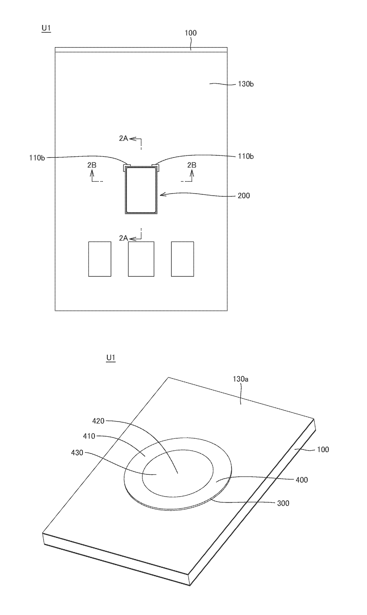
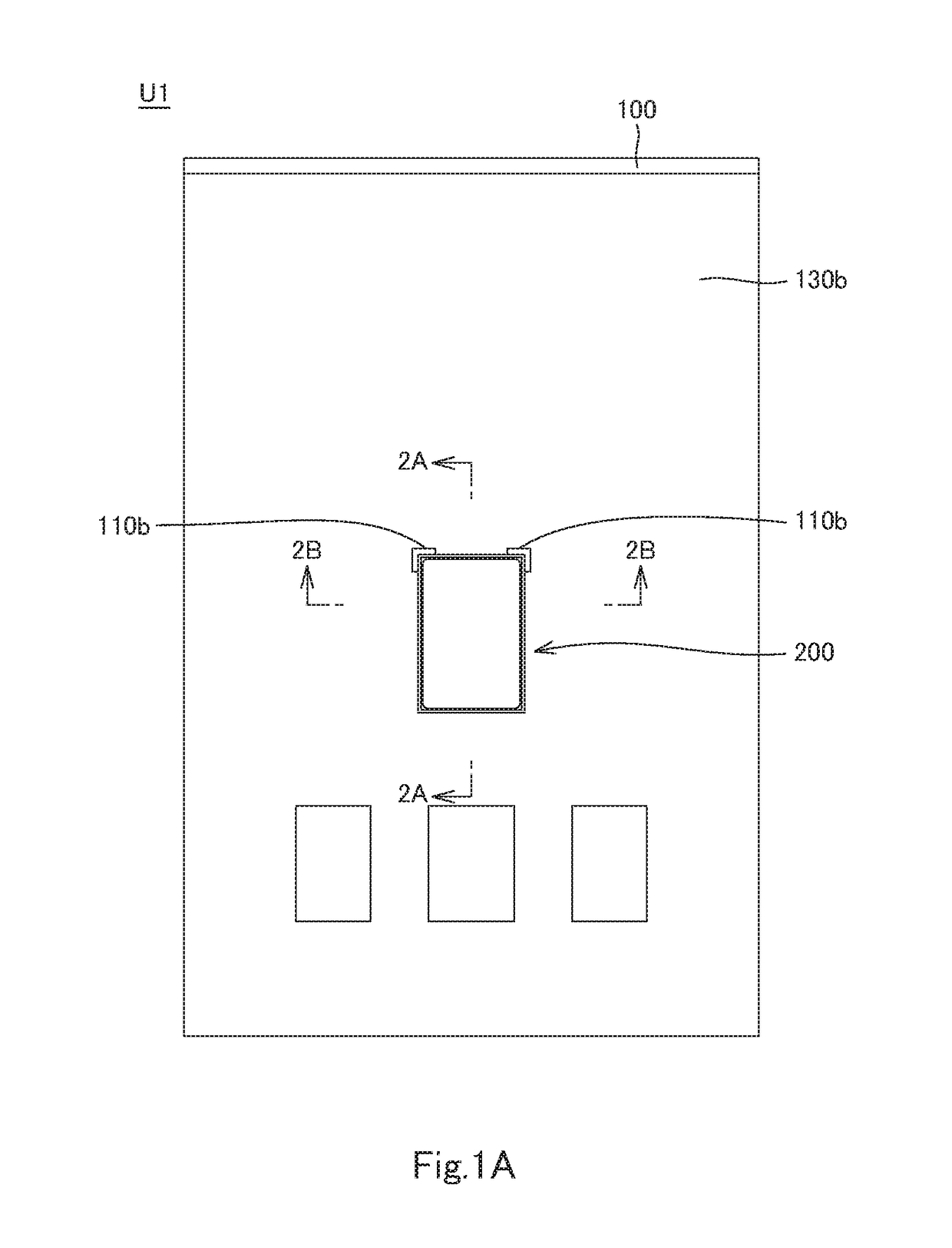
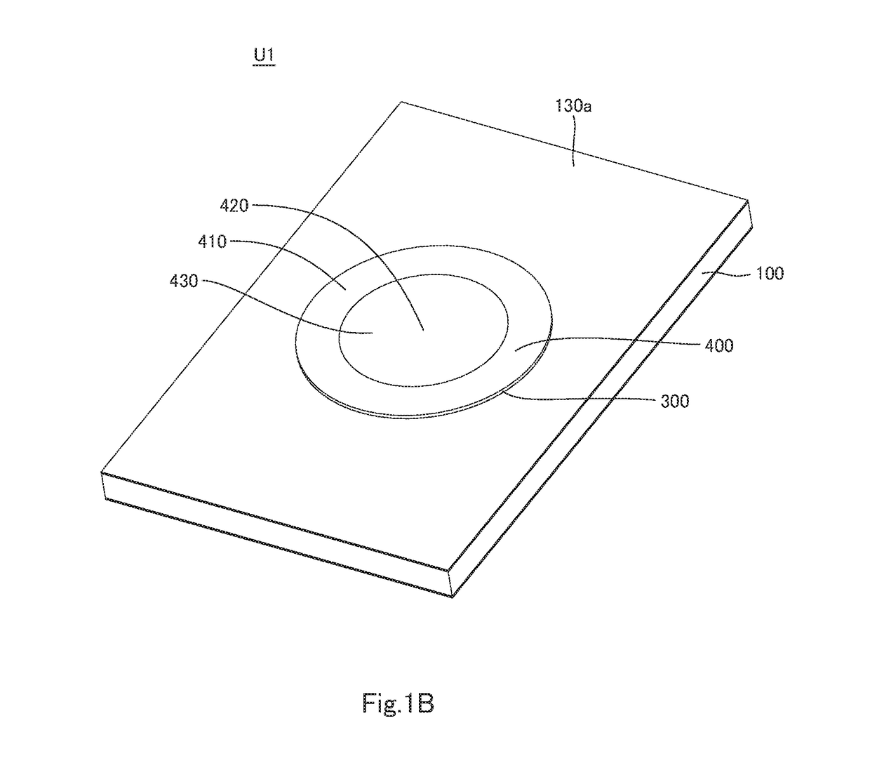
[0033]The following describes a microphone unit U1 (which may be simply referred to as the unit U1) according to a plurality of embodiments including the first embodiment of the invention, with reference to FIGS. 1A to 3B. FIGS. 1A to 3B show the unit U1 according to the first embodiment. The unit U1 includes a substrate 100 and a microphone 200. It should be noted that the Z-Z′ direction indicated in FIGS. 2A to 2B is the thickness direction of the substrate 100. In the Z-Z′ direction, the Z direction is one side of the thickness direction, and the Z′ direction is the other side of the thickness direction.
[0034]The substrate 100 includes a first face 101, a second face 102, and a through-hole 103. The first face 101 is the Z-direction-side face of the substrate 100, and the second face 102 is the Z′-direction-side face of the substrate 100, i.e. the face opposite to the first face 101. The through-hole 103 extends from the first face 101 to the second face 102 through the substrate...
second embodiment
[0062]The following describes a microphone unit U2 (which may be simply referred to as the unit U2) according to a plurality of embodiments including the second embodiment of the invention, with reference to FIGS. 4 and 5. FIG. 4 illustrates the unit U2 of the second embodiment. FIG. 5 illustrates a variant of the unit U2 of the second embodiment.
[0063]The unit U2 has the same configuration as a unit U1, except that the unit U2 includes a fixing member 300′ of different configuration from that of the fixing member 300 of the unit U1. Accordingly, only the differences will be described, and those features of the unit U2 which generally correspond with those of the unit U1 will not be described in detail.
[0064]The fixing member 300′ is constituted by an adhesive portion 320′ only. The adhesive portion may be, for example, a double-sided adhesive tape or an adhesive layer. The adhesive portion 320′ has an inner size that is larger than the size of the through-hole 103 of the substrate ...
third embodiment
[0077]The following describes a microphone unit U3 (which may be simply referred to as the unit U3) according to a plurality of embodiments including the third embodiment of the invention, with reference to FIGS. 6A to 6F. FIG. 6A illustrates the unit U3 of the third embodiment. FIGS. 6B, 6C, 6D, 6E, and 6F respectively illustrates a first, second, third, fourth, and fifth variant of a film 400′ of the unit U3 of the third embodiment.
[0078]The unit U3 has the same configuration as the unit U1 or U2, except that the film 400′ of the unit U3 has a different configuration from that of the film 400 of the unit U1 or U2. Accordingly, only the differences will be described, and those features of the unit U3 which generally correspond with those of the unit U1 or U2 will not be described in detail.
[0079]The film 400′ includes a first portion 410′, a second portion 420′, and a third portion 430′. The first portion 410′ is fixed to the fixing member 300 (see FIGS. 6A to 6F) or 300′ (see FIGS...
PUM
 Abstract
Description
Claims
Application Information